Navigation
Install the app
How to install the app on iOS
Follow along with the video below to see how to install our site as a web app on your home screen.
Note: This feature may not be available in some browsers.
More options
Style variation
-
Congratulations TugboatEng on being selected by the Eng-Tips community for having the most helpful posts in the forums last week. Way to Go!
You are using an out of date browser. It may not display this or other websites correctly.
You should upgrade or use an alternative browser.
You should upgrade or use an alternative browser.
Bridge failure near Albany NY 15
- Thread starter bridgebuster
- Start date
- Status
- Not open for further replies.
I am reminded of the late Henry Petroski's book "Engineers of Dreams" where errors are repeated over and over again. Ending those repeats was the reason he gave for writing it.
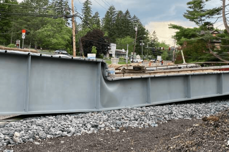
I'm sure someone saw the wrinkle in the web and thought - maybe it was there yesterday, so it's OK. They want that to be the case rather than stopping the construction schedule to find out.
Henry Petroski died last month, so he didn't get to see another repeat that should have been avoided.
I think a full semester course on engineering failure and why it seems to be based on humans and a sort of blindness should be required.
(Personal experience: just recently saw a video about soda bottle sheet plastic holders having perforations and tear-off strips. Even though I diligently cut the rings and handle hole with scissors because somewhere a sea turtle might get caught, it's a detail that had been entirely invisible to me. I thought they were simply die cut with no perforations at all. It's easy to be blind if the factor is one that isn't being looked for. No doubt they were told to make the span look like the one the railroad used and just never noticed the supports or a moment diagram for the old one.)
-
1
- #42
JohnRBaker
Mechanical
I've read several of Professor Petroski's books and one of the first bits of insight that I gained from that was an appreciation for his contention that there is much to be gained from studying failures. I think he once put it that you'll learn more from a single failure than a dozen successes. And with that in mind and considering the subject of this thread, he spent a lot of time explaining about the inevitability of bridge failures, because, as he explained, virtually every bridge ever built in the world was paid for with public money, i.e. someones tax dollars, and so the impetus was to always go with the lowest bidder who would have looked at the last successful design and felt that if he could just reduce the safety factor by a small amount, that he could build the bridge for less money and thus would be able to win the contract. And this process would continue until one day, the next bridge to be built would fail. At that point, the industry would go back to the last one the didn't fail, and that design would become the industry standard. He postulated that this cycle would play out for every unique type of bridge design, and that any new style would be condemned to this same 'shave the safety factor' until a failure occurs scenario. And of course, the example that he used to make his point was "Galloping Gertie", the Tacoma Narrows suspension bridge which failed in 1940. I don't think there's been a collapse of a significant suspension bridge since that incident, despite hundreds having been built around the world since 1940.
John R. Baker, P.E. (ret)
Irvine, CA
Siemens PLM:
The secret of life is not finding someone to live with
It's finding someone you can't live without
John R. Baker, P.E. (ret)
Irvine, CA
Siemens PLM:
The secret of life is not finding someone to live with
It's finding someone you can't live without
LittleInch
Petroleum
Are we missing the bleeding obvious here? Was there supposed to be a support, either temporary during concrete work or permanent?
What are the three odd looking things on top of the new wall?

But if not I stick to my premise that someone found the old drawings of the bridge and said to a fabricator, give me something that looks the same as its a replacement. Someone else then decided to dig the underpass deeper and not put the retaining walls / supports back in. But no one told the fabricator....
Remember - More details = better answers
Also: If you get a response it's polite to respond to it.
What are the three odd looking things on top of the new wall?

But if not I stick to my premise that someone found the old drawings of the bridge and said to a fabricator, give me something that looks the same as its a replacement. Someone else then decided to dig the underpass deeper and not put the retaining walls / supports back in. But no one told the fabricator....
Remember - More details = better answers
Also: If you get a response it's polite to respond to it.
LittleInch
Petroleum
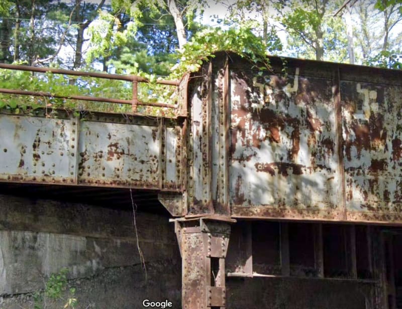
The old one is very clearly three separate structures joined together and totally reliant on the support for vertical load.
I take back my comment about them being the same, but still think someone forgot to tell the designers the supports wouldn't be there...

Remember - More details = better answers
Also: If you get a response it's polite to respond to it.
I take back my comment about them being the same, but still think someone forgot to tell the designers the supports wouldn't be there...

Remember - More details = better answers
Also: If you get a response it's polite to respond to it.
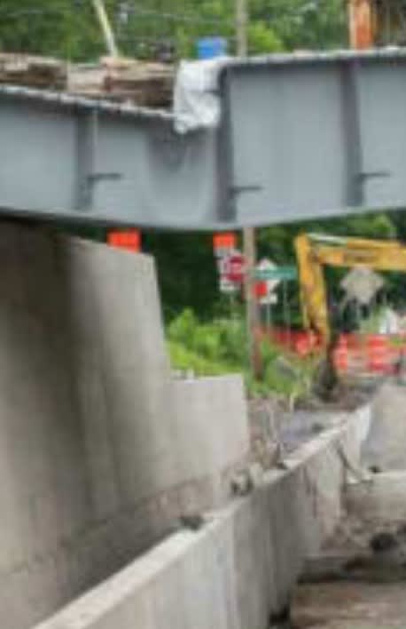
There were what appeared to be temporary supports for the span; you can see that the buckled section had such a support in the first picture I posted.
TTFN (ta ta for now)
I can do absolutely anything. I'm an expert! faq731-376 forum1529 Entire Forum list
TTFN (ta ta for now)
I can do absolutely anything. I'm an expert! faq731-376 forum1529 Entire Forum list
Lomarandil
Structural
Sure, but a temporary support to what end? Certainly they weren't intending to make the through-girders composite with a deck at the bottom flange.
-
1
- #48
LittleInch
Petroleum
Irstuff.
Your picture is the other side and it looks like a proper sypport to me.
So I think they were missing sorts on the other side which collapsed
Remember - More details = better answers
Also: If you get a response it's polite to respond to it.
Your picture is the other side and it looks like a proper sypport to me.
So I think they were missing sorts on the other side which collapsed
Remember - More details = better answers
Also: If you get a response it's polite to respond to it.
The "other side" with the blocks underneath already experienced buckling of the web; probably why someone made an impromptu support.
Other photos / Google maps street view show proper bridge rocker plates at the ends of the bridge and no other intermediate supports.
Other photos / Google maps street view show proper bridge rocker plates at the ends of the bridge and no other intermediate supports.
- Thread starter
- #51
bridgebuster
Active member
JohnRBaker
Mechanical
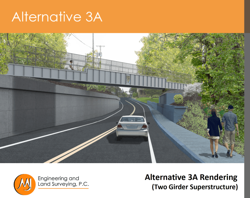
As seen in this image from the slideshow, it appears that they assumed that they would need NO intermediate supports, as was there in the original and the first alternative replacement proposal:

John R. Baker, P.E. (ret)
Irvine, CA
Siemens PLM:
The secret of life is not finding someone to live with
It's finding someone you can't live without

John R. Baker, P.E. (ret)
Irvine, CA
Siemens PLM:
The secret of life is not finding someone to live with
It's finding someone you can't live without
This design epitomizes the modern absurdity of asthetics over function. The older structure looked the way it did for functionality in the face of then current methods and materials.
It fosters the belief that we can adequately analyze our way out of any eventuality the asthetics throw at us, even with sufficient forethought.
And with that, I've used all my big words for the day.
It fosters the belief that we can adequately analyze our way out of any eventuality the asthetics throw at us, even with sufficient forethought.
And with that, I've used all my big words for the day.
-
1
- Thread starter
- #54
bridgebuster
Active member
Sometimes it's appropriate to put something in to suggest what was there. However, in this case, the aesthetics are horrible. I don't see a bridge; I see a straw hat. Even though the dap isn't very deep, the hard vertical edge, joining two horizontal hard edges, holds my attention rather than naturally allowing my eye to go through the rendering. The fence compounds the felony. That's the landscape painter in me talking.![[tiphat] [tiphat] [tiphat]](/data/assets/smilies/tiphat.gif)
![[tiphat] [tiphat] [tiphat]](/data/assets/smilies/tiphat.gif)
Should you be interested, it appears this bridge was designed by:
MJ Engineering and Land Surveying, P. C.
A Professional Corporation, I suppose.
Here's their "about" page:
And here is their bridge design page:
They note they have inspected 4500 bridges in New York State. I'm sure they did an excellent job of it.
I do wonder if they have any civil engineers on staff, and their education and experience.
spsalso
It's interesting they didn't consider two other possibilities:
Throw a cheap-ass flat bridge across the road (since it's only carrying pedestrians) and then add a decorative fake bridge girder on each side. The fake pieces could be made out of styrofoam or another high-tech material. Carbon fiber!! Apparently that solves almost anything, at least at one atmosphere of pressure.
And then there's my true favorite: jack the old bridge up a couple of feet. That would be unacceptable for railroad use, but we're talking pedestrians here. Climbing that extra two feet of grade would be healthful. I'll also note that since the live load is going from maybe 200,000 pounds down to 1000 pounds, the load on the old piers and abutments would be dramatically reduced. And they ALREADY own the bridge--it would have been FREE. And done in about a month. With long lunch breaks.
spsalso
And here, by the way, is another partner in this project: the check writers
Note that the road will be closed until July 31.
spsalso
Note that the road will be closed until July 31.
spsalso
The bridge is required to support emergency vehicle traffic in addition to its use for pedestrians, in particular H-10 vehicles, 20,000 pounds.
The location of the supports were one of the two main problems - jacking the bridge up fails to address that.
The present supports are located such that the sidewalks aren't ADA compliant.
I don't know what a "flat bridge" is.
Interesting document:
I suspect the majority of the steel can be saved if they cut the top plates off the shallow sections and either extend the deep section or meet the deep section with a taper and fill in the web to match. They can use the majority of the cap from the shallow section. When they are doing that they can cut out the buckled web and jack the rest back up, not in that order. It won't look so good as the factory finish, but with so much of the roadbed in place putting the beams back on the truck or dropping in new ones is off the table. At least the foundations for the supports are likely to remain in place.
"The bridge is required to support emergency vehicle traffic in addition to its use for pedestrians, in particular H-10 vehicles, 20,000 pounds."
So it is a roadway, not a pedestrian bridge. Still, the live load is a lot smaller than the rail load, and the old bridge could have handled that load.
"The location of the supports were one of the two main problems - jacking the bridge up fails to address that."
What were those two main problems?
"The present supports are located such that the sidewalks aren't ADA compliant."
I see from the drawings that the sidewalk had to be widened from 3' - 8" to 5', a distance of 16". Since it has been deemed that only one sidewalk is required, the abutment on one side could have been moved that 16". Note that the main load of the old bridge did not land on the abutments, but was on the piers. So they could have achieved the ADA compliance by modifying the abutment on one side.
What exploration was done on this approach?
spsalso
"What were those two main problems?"
If you don't figure it out for yourself it won't mean as much.
Each abutment is a concrete wall that appears to be 11 feet high (not including foundation,) nearly 100 feet long, and around 4 feet thick at the base.
Is there a reasonable suggestion to "modifying the abutments" when those are what is holding back the walls of the cut?
- Status
- Not open for further replies.
Similar threads
- Locked
- Question
- Replies
- 69
- Views
- 4K
- Replies
- 4
- Views
- 2K
- Question
- Replies
- 27
- Views
- 28K
- Replies
- 1
- Views
- 5K
- Replies
- 13
- Views
- 13K

![[sad] [sad] [sad]](/data/assets/smilies/sad.gif)
