Continue to Site

Eng-Tips is the largest engineering community on the Internet

Intelligent Work Forums for Engineering Professionals

  • Congratulations GregLocock on being selected by the Eng-Tips community for having the most helpful posts in the forums last week. Way to Go!

Bridge failure near Albany NY 15

Status
Not open for further replies.

bridgebuster

Active member
Jun 27, 1999
3,969
I think they forgot some stiffeners [sad]

Picture1_tzflwq.png


Link
 
Replies continue below

Recommended for you

Little different shot showing beams transverse to the main span.

Transverse_Beams_x46gpv.png
 
DanKile, I noticed that also. In the renderings and drawings the stiffeners are symmetrical with the change in depth, in the delivered beams they are not. Odd. Design was changed? Fab error not caught?

I suppose the lawfare will provide answers :)

The problem with sloppy work is that the supply FAR EXCEEDS the demand
 
LittleInch (Petroleum) 17 Jul 23 14:58 said:
But but but the last one stood for 100 years[!]
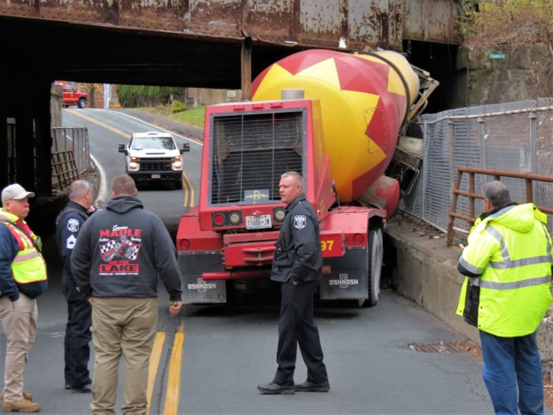
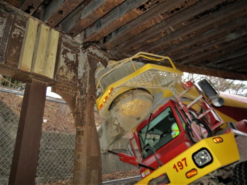
Yeah. And it could stop a concrete truck. Why replace it?

rawImage_i9kan6.jpg


IMG_2239_zwqc6k.jpg
 
I especially like those three additional wood posts. Or whatever those added structural members would be called.

Note that the steel post immediately below them is a bit younger than 100 years.

From this last view, I do now suspect that keeping the old bridge was not feasible. Too bad.


spsalso
 
Based on 3DDave's link to the proposed options, it doesn't look like they actually chose 3A, since 3A ostensibly had the taller section extended to span past the entire gap, which is not what they built. It looks like they did something in-between the "refurbishment" alternative 2A and 3A, since the tall section is longer, but not as long as the 3A shows it's supposed to be.

TTFN (ta ta for now)
I can do absolutely anything. I'm an expert! faq731-376 forum1529 Entire Forum list
 
The 3A section doesn't extend to the new bridge supports. The section view cuts off the low-height sections. In some literature they suggest the bridge will be at 0 degrees across the road, but it still followed the original angled path.
 
Also why does the thicker section not span between the two abutments evenly. It seems one side or the other has an overhang but it isn't even?

Lots of things to go wrong here so will be interesting to see, if indeed we ever hear why they managed to get it so badly wrong...

Remember - More details = better answers
Also: If you get a response it's polite to respond to it.
 
The original bridge was a skewed bridge.

The new one was not. You can see that in the photos in the linked article:


You can also see that the new metalwork was not done to represent the old skewing. You can also see that the location of the stiffeners is asymmetrical. Well, actually, they ARE. Note that the spacing between them remains constant over the span. It's the decorative swoop that doesn't match THEM.


There is quite a good collection of big photos on the above site.


Note also that the new bridge was a single span bridge, and was not meant to rest on the top of the retaining walls. The old bridge was a three-span skewed bridge, and thus needed two intermediate supports.


spsalso
 
The skew over the road cut is clearly visible in those photos.

The original was skew to the road cut and also the cross members were skew to the main beams. The underside cross members aren't skew to the main beams in the new one. The main beam decorative change in depth matches the skew to the roadway.

(edit to note what it is an angle to)
 
There is also the potential that the bridge was only analysed in the as built condition where I can only think that all that heavily reinforced concrete added to the strength / stiffness of the bridge?

Only problem was that they forgot that until the concrete set it was just a weight and did zero for the structural stiffness of the bridge. It is noted that they seem to have started pouring from the end which buckled. But they hadn't added any temporary supports under the bridge like they have done for the other side.

And sym P lee - please check out this drawing - the option being built was 3A
The bridge is clearly skewed versus the road axis.

Remember - More details = better answers
Also: If you get a response it's polite to respond to it.
 
A pretty reasonable suggestion that the bridge is intended to be essentially a reinforced concrete bridge with a decorative girder, and they forgot that before the concrete sets it is just a dead weight and the girder needs to be able to take that load. I can't see how anyone would imagine that girder design alone would take a high load without support near those elevation changes.

> "The present supports are located such that the sidewalks aren't ADA compliant."

This seems like a case where common sense should have been applied - particularly as the proposal removes one of the footways entirely, surely that is *worse* for pedestrians.
 
The girders had purlin/joist beams spanning between them and presumably the deck was designed to span one-way between purlins. Either way, I don't think there was any effective compression flange bracing since it was designed as an upstand girder.
 
See for a post collapse photo of the 2002 failure. It looks like the open channel wasn't stiff enough and the internal cross members buckled trying to resist the torsion from the initial twist due to deflection. Had they never handled a long piece of gutter? Twisty dang section. I haven't found the final report.

In 20 years how many have retired from that company? This is one of the cautions that Henry Petroski made in his book about bridges - people leave and the industry forgets.
 

A lengthy doctoral analysis of bridge failures, including the Marcy bridge.

Bracing of steel bridges during construction
Theory, full-scale tests, and simulations
Hassan Mehri
Faculty of Engineering
Lund University

Perhaps AASHTO standards can require that all participants read Engineers of Dreams and point out any similarities to the organization or type of construction as part of the analysis/proposal of bridges prior to starting construction.
 
Nobody was hurt in this collapse, right? I think the large offset from the bearing supports to the face of the retaining wall is probably what saved their lives. IT only fell a foot or so then stabilized.
 
There appears to be some here who think the bridge would have held if the steel beams had been adequately supported until the concrete set.

I s'pose.

But notably missing on site was anyone who knew that. In particular, no one from MJ.

I wonder if it was mentioned in the plans. Or perhaps there was a drawing of the temporary supports, and the builders lost that page.


spsalso
 
It baffles me that a decorative girder could somehow have been holding up the concrete and still be intended as decorative? If the girder is there intentionally to support the concrete while it's wet, it's a design fuckup, and if it wasn't meant to support the concrete during construction, did the contractor just decide it was good enough to support the formwork? I have trouble believing the latter could happen.

----------------------------------------------------------------------

Why yes, I do in fact have no idea what I'm talking about
 
Fortunately could be a relatively easy fix. Cut out damaged section, fab new section (with proper reinforcement) and weld or rivet it in place. Could be done in situ. But who knows what the concrete already poured did.

That was a lot of rebar on that concrete deck. Could see where the engr factored that into the strength of the span. But until it cures somewhat, it is simple weight and no help with the structure. May be a contractor error not providing temporary shoring????
 
With the web so thin, it does seem like the girders were decorative. Might have been a good idea to add them last, to lessen damage during construction.

Oh, yeah. That concrete slab would do nicely for the "flat bridge" I mentioned earlier.

spsalso
 
Status
Not open for further replies.

Part and Inventory Search

Sponsor