Eng-Tips is the largest engineering community on the Internet

Intelligent Work Forums for Engineering Professionals

Bridge failure near Albany NY 15

Status
Not open for further replies.

bridgebuster

New member
Jun 27, 1999
3,962
0
0
US
I think they forgot some stiffeners [sad]

Picture1_tzflwq.png


Link
 
Replies continue below

Recommended for you

Various references indicate that reinforced concrete slabs, simply supported at the ends, should have a length to thickness ratio under 30:1. For this 120 foot span that would require a slab 4 feet thick, or about what the shorter sidewall stands at. I think that might produce a bump at the end.

In addition, many state DOT guides limit such spans to between 30 and 45 feet, depending on application, as other arrangements make more efficient use of materials. This bridge is 3-4 times that recommended length.

The slab they were pouring isn't anywhere close to the thickness required for a concrete slab bridge. If it was, the form work would be underneath and the rails bolted in place after the slab had cured and the form work stripped. They would not be using a paving machine to lay down a 4 foot thick pour of concrete.

 
Maybe it was part supported?

We're all guessing, but it does look like a pretty thick piece of concrete with a LOT of re bar

Remember - More details = better answers
Also: If you get a response it's polite to respond to it.
 
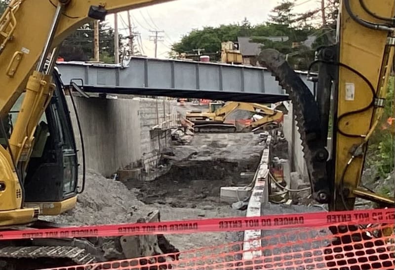
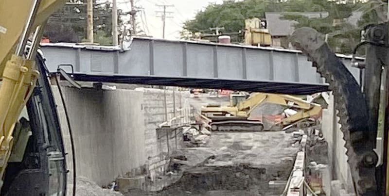
The apparent quantity of rebar is likely a trick of the angle of the shot. At that angle, you're seeing much of the 130ft span compressed down to a space that looks more like 5 or 6 feet.

Everything about this makes perfect sense:

1) Existing, historic railroad bridge is in disrepair and needs to be replaced. It was originally comprised of three individual spans with interior supports; the center being the longest and the tallest. Instead of supporting trains, though, now it just needs to support pedestrians (and maybe an ambulance - I've only had to consider that for pedestrian bridges when there isn't a reasonable alternative for emergency crews to reach pedestrians in distress).

2) The held a design charette to get input from stakeholders (note that non of the documents anyone has linked to are in any way 'final' or 'for construction' - they are all preliminary concepts meant to a)provide a sort of proof of concept that it could work and b)provide the bare minimum visualization necessary). I'm not a bridge guy, but historic building structures are my thing, so I'm accustomed to working with architectural review boards and departments of historic resources and the like. This is how they think: keep the old stuff if at all possible; if not possible, then the new must evoke the old to the greatest extent possible. Since keeping the old one was not at all practical, they went with a new version that looked similar. Nobody forgot to install supports. They weren't installing the girders wrong. The goal was not an efficient structure but a structure that reminds people of the old one. When doing these types of projects, it requires us to ignore some parts of logic lest we go insane railing against it.

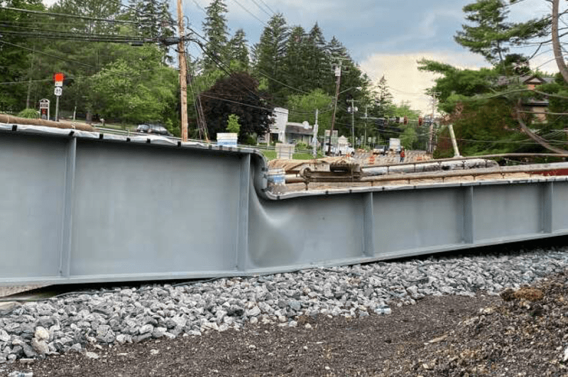
3) Skinny webs really aren't a problem. They're used all the time to improve material efficiency. That's what those stiffeners are for. It doesn't take much to handle the shear in a steel girder like that. The problem is the detailing at the transition. A thicker web might have saved them, sure, but a more efficient method would have been to detail the stiffeners at that transition better. I daresay that's why the opening line of the thread from bridgebuster was "I think they forgot some stiffeners." An oversight in consideration of web buckling at that transition by the design engineer is the most likely culprit.
 
Agreed, but I suspect it was a combination of local web buckling and perhaps some influence from global LTB. There really wasn't anything bracing the top flange, so it was able to move laterally which is just another source of instability. Kind of a moot point since the local buckling probably would have happened regardless of whether the compression flange was braced or unbraced.
 
The transition was the weak point.
However, if the concrete was in place and cured, the buckling could not have taken place unless the concrete compressed or buckled.
As regards to the failure to shore up prior to pouring concrete;
Someone didn't RTFI. (Or the FI did not exist.)

--------------------
Ohm's law
Not just a good idea;
It's the LAW!
 
In the picture with all the rebar exposed I notice the small tragedy - those two workers are carefully applying a plastic sheet so the beam will be protected from the concrete splatter. An attention to deal that was soon to be for naught. It looks from other photos they did both sides. I salute you, conscientious workers.
 
"However, if the concrete was in place and cured, the buckling could not have taken place unless the concrete compressed or buckled."

If one looks at the top chord design it was made in the shape that a buckled top chord would have. The concrete's failure modes would have been as insufficient to preventing this as noting that the bottom chord would have to bend to allow this buckling. Worse, whatever contribution there is from the thin pavement could have concealed the lack of strength until it was called upon for use by an emergency vehicle and collapsed into truck traffic below - see the Hyatt Regency walkway collapse in Kansas city.
 
The concrete deck was at a distance above the lower flanges.
See the cross beams that support the concrete in azcats post.
azcats (Structural)
17 Jul 23 15:00
Little different shot showing beams transverse to the main span.
With the concrete placed above the lower flange, either the concrete would have to be compressed or the lower flange would have had to stretch before the panel could buckle.
I am not saying that the bridge would have withstood the design load, but with the concrete placed and cured, the bridge would have been able to support much more weight before collapsing.

--------------------
Ohm's law
Not just a good idea;
It's the LAW!
 
What is described above is much of the guidance I have seen on upturned girder bridges - you must rationalize the stringers between the girders can provide a torsional restraint. It is possible with just the stringer connection alone but generally would need a stiffener that aligns there up to the top flange so that part of the web and stiffener act as a cantilever from the stringer to girder moment connection. It needs to be both strong and stiff enough and with that thin web I would think a stiffener would be required to make that work out.

Looking at the photos it does appear stringers may align with stiffeners so that may have been the intent but its not clear.
 
One of the images of beams on trailers clearly shows a 6-hole pattern in each stiffener. For attachment of stringers?

Some images seem to show a series of clips running down the outside of one beam, but not the opposite one. Wish we could see the opposite side of each beam in DanKile's post of beams on trailers :)

The problem with sloppy work is that the supply FAR EXCEEDS the demand
 
I don't think that 6 bolt connection would have enough rotational stiffness to stabilize the top chord through the stiffener. It's essentially a pin connection, unless there's more to the connection than those 6 bolts. But I doubt there was.
 
In this image:

Railtrailcollapse071223-13_pwszxr.jpg


You can see that the steel crossmembers of the bridge are right above the lower flange. It appears that this bridge is/was not a half-through bridge.


It would be swell for the plans for this bridge to be publicly available. It is, after all, owned by the public.


spsalso
 
The concrete, when set, would have acted above the bottom flange at an elevation above the thickness of the cross members and somewhere internal to the thickness of the concrete slab.
Given the relative incompressibility of concrete, the slab (when set) would have provided a lot of stiffening.

--------------------
Ohm's law
Not just a good idea;
It's the LAW!
 
"The concrete, when set, would have acted above the bottom flange at an elevation above the thickness of the cross members and somewhere internal to the thickness of the concrete slab."

I think it would have done that when it hadn't set, also. Which kinda looks like what happened to take the bridge down.

I'm having trouble envisioning that load path.

"Given the relative incompressibility of concrete, the slab (when set) would have provided a lot of stiffening."

Would that stiffening have held up the bridge? How?


spsalso
 
Status
Not open for further replies.
Back
Top