Continue to Site

Eng-Tips is the largest engineering community on the Internet

Intelligent Work Forums for Engineering Professionals

  • Congratulations KootK on being selected by the Eng-Tips community for having the most helpful posts in the forums last week. Way to Go!

Can Position Tolerance and Run-Out can be applied together? 2

Status
Not open for further replies.

pandeydhiraj

Mechanical
Dec 3, 2013
5
In any case can Position Tolerance and Run-Out can be applied together to a Feature of Size or plane surface.
I know both are location control doesnot make sense if applied to same feature, but just want to make sure about this thing.
Thanks
Dhiraj
 
Replies continue below

Recommended for you

pandeydhiraj,

Can they? Maybe. Should they? Probably not - at least if you're talking about total runout (I'd say the same likely holds for circular runout but it can be a little more difficult to pin down so I don't want to make the same blanket statement). Total runout will almost always be the tighter control, so I would be hard pressed to think of a situation where a feature would pass in total runout, but fail position. One thing to keep in mind is that runout is always RFS, so while MMC/LMC can be applied to position to take advantage of bonus tolerances the same cannot be said for runout.

See the attached resource for some examples of position vs runout (concentricity is included as well).

pandeydhiraj said:
can be applied together to a Feature of Size or plane surface.
Also note that position CANNOT be applied to a purely planar surface while runout can. (ie: axial faces on Fig 9-4). Position can only be applied to a FOS.

Edit: spelling
 
 https://files.engineering.com/getfile.aspx?folder=4ed27093-6600-455e-a4de-7310fc019112&file=newsletter_-_pass_fail_-_concentriciy_runout_and_position.pdf
Within ISO, position may be applied to a planar surface. Perhaps the OP is following ISO.

But that aside, I suppose position and total runout could be applied together. Since runout is a composite control of location, orientation, and form, the application of an additional position tolerance would isolate the location and orientation aspects of the axis. Runout will still be controlling form of the surface, and it would be a larger tolerance than position.
 
JP,

I concede that if the runout tolerance is larger than the position tolerance, they could be applied together which is why I said only "probably not" instead of outright "no". Suffice to say that is not the typical application, correct? I would think that in the majority of circumstances it would be one or the other, not both.
 
Belanger said:
Since runout is a composite control of location, orientation, and form, the application of an additional position tolerance would isolate the location and orientation aspects of the axis. Runout will still be controlling form of the surface, and it would be a larger tolerance than position.

What I learned from this forum (a few months ago......, maybe a year now) is that the total runout will NOT control the surface location.


Well, I would just say the above mentioned discussion is just counterintuitive, at least for me......, but it is what it is.....live and learn.
 
Agreed, chez311. I've never seen the situation that the OP is asking about. I was just thinking from the theory point of view.
 
If we take Fig. 8-26 / 2009 page 178, and replace Ø20 basic with 20±0.25 and add a position callout for the newly direct toleranced dimension, then would you think this scheme is valid or not? Keep total runout unchanged, just the "in between profile" may not be applicable for the feature Ø20 diameter (should stop after R10 basic)

So, runout and position are applicable to the same feature. Is this scheme valid? If not, why not?

 
greenimi,

I think JP and I both agreed above that position and runout/total runout could probably be applied to the same feature, and would be functional (ie: both controls actually serve a purpose instead of one overriding the other) if the runout tolerance were larger than the position tolerance. We also agreed that while valid, it would be at least somewhat uncommon to see something like this.

I don't think anyone said it would be invalid. Does that answer your question? If not, could you maybe clarify your question a little?
 
chez311 said:
if the runout tolerance were larger than the position tolerance
Why runout cannot be refinament?

Looks like 8-26 is treating runout as refinament, don't it?
 
greenimi,

Well it depends on how we define refinement, doesn't it? I would almost argue that a runout tolerance larger than the position tolerance could be a refinement - it would limit surface variations that a position tolerance would otherwise allow.

If you mean refinement as in a runout tolerance smaller than the position tolerance, then I don't believe this is feasible. As far as I can tell, with everything else being equal (ie: same DRF) the runout tolerance would always be tighter than the position tolerance, which would render position redundant. If you can think of a case where this is not true, I'd be interested to see it.
 
chez311 said:
If you mean refinement as in a runout tolerance smaller than the position tolerance, then I don't believe this is feasible. As far as I can tell, with everything else being equal (ie: same DRF) the runout tolerance would always be tighter than the position tolerance, which would render position redundant. If you can think of a case where this is not true, I'd be interested to see it.

Take a look at the attached picture. It was created by pylfrm about 2 years ago for the purpose of a slightly different discussion:

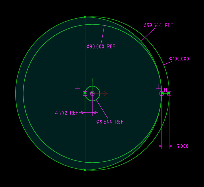
Imagine that what you see is a cylinder (of nominal size of dia. 95 +/-5) produced with actual total runout error of 5, but at the same time having actual position error of approximately 9.544. Datum axis is at the origin of the coordinate system.

Link to the picture:
 

New and improved version, with circles up to 700% more circular:

1_crop_3_wjgvz5.png


pylfrm
 
Dear Belanger (Automotive)

Quote (Belanger (Automotive)14 Jan 19 14:59)
"But that aside, I suppose position and total runout could be applied together. Since runout is a composite control of location, orientation, and form, the application of an additional position tolerance would isolate the location and orientation aspects of the axis. Runout will still be controlling form of the surface, and it would be a larger tolerance than position."

I want to ask how in terms of inspection how you will isolate the form of the surface when checking Runout as full indicator reading,will take care of Form, orientation and location.
and since you are mentioning that Runout will be larger so refinemnts will be left for the position applied, and if so how only refinement can be checked for position too.
If position is applied at MMC the functional gauge will take care of every thing orientation and location.
So my concern is in terms of inspection application of Runout and Position together doesnot make sense.
Thanks
Dhiraj
 
For an example of a feature that could benefit from a tighter position than runout, how about a hydraulic manifold with a very deep oil gallery?

Say the gallery is ø10mm and 300mm deep, and that the position of the entrance to the gallery - or the hole on the face of the manifold - is important to ensure mechanical compatabillity with a fitting. It might be desirable to control the position of the hole location with a tolerance of 0.2mm while allowing the machinist more leeway to drill the deep hole since the hydraulic fluid will not care if there is a runout of 3mm.

Having said that, if the position would still be controlling the orientation of the axis then maybe this wouldn't achieve the desired result.

GSTP

Graduate Mechanical Design Engineer
UK
 
pmarc/pylfrm,

Thank you for the reference - I had actually read through that thread a while back but had forgotten about it. Now I see its implications for both straightness and position vs. runout. Seems to be mainly in the difference that runout directly controlls the surface vs. position controlling the axis formed by the UAME (in this case the circular/cylindrical feature of smallest size). Very edifying - thank you!

I mapped it out in CAD and was about to say that I noticed was that if the arc on the right side of the figure (shown as 99.544 REF) is changed to be as close to 100 as possible the linear deviation approaches 5 which makes the size of the position tolerance zone nearly 10, or almost exactly twice the runout. HOWEVER am I correct in assuming that you have evaluated the case shown because that is the largest UAME that approaches 100 still having opposed points 180 degrees apart? Ie: the case attached would NOT be valid because the arc of size 99.99 does not have points which satisfy that?

 
 https://files.engineering.com/getfile.aspx?folder=850bfa8e-47d8-4ae3-a667-4e06cbf3bea7&file=runout_vs_position.JPG
pmarc,

What makes you think that your illustration represents position error of 9.544?

"For every expert there is an equal and opposite expert"
Arthur C. Clarke Profiles of the future

 
It's the fact that the axis of the smallest possible cylinder circumscribed on that actual feature (UAME of the feature) is offset 4.772 from the datum axis. If the offset is 4.772, then the actual position error is 2*4.772.
 
pmarc,

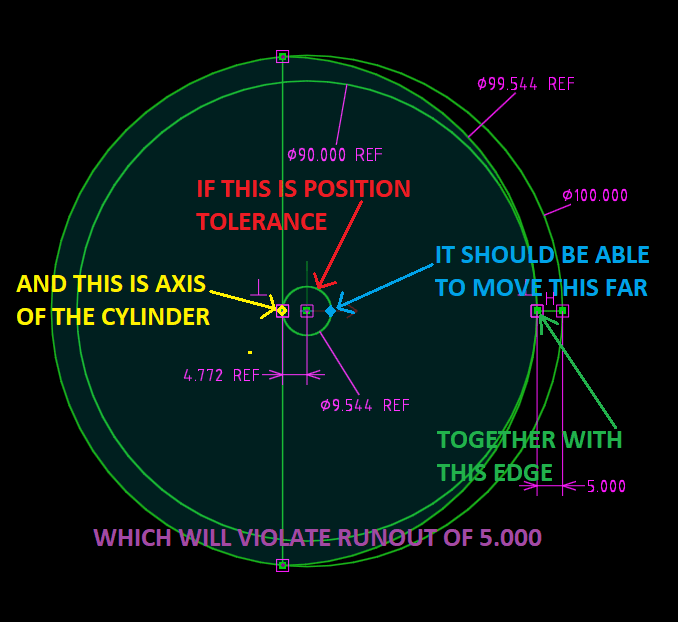
It looks like your axis is in the wrong position:

1_crop_3_wjgvz5_fuw8xo.png


"For every expert there is an equal and opposite expert"
Arthur C. Clarke Profiles of the future
 
The circle in the center is not a position tolerance. It represents the actual position error of a single as produced cylinder. This cylinder, when rotated about the datum axis, will give total runout error of 5.
 
OK, Let put it this way:

-It is common knowledge that position tolerance may be explained either in terms of the surface of the actual feature or in terms of size and the resolved geometry (center point, axis, or center plane) of the applicable (mating or minimum material) actual envelope (Also known as surface interpretation and the resolved geometry interpretation)

-It is also common knowledge that for MMC and LMC callouts, these explanations are not equivalent. It is possible to have part that will be accepted one way and rejected the other.

Runout is a strictly surface control so it would be incorrect to compare it with resolved geometry (axis of inscribed / circumscribed cylinder)

This is why I will be convinced when I see surface-to-surface comparison


"For every expert there is an equal and opposite expert"
Arthur C. Clarke Profiles of the future

 
Status
Not open for further replies.

Part and Inventory Search

Sponsor