Continue to Site

Eng-Tips is the largest engineering community on the Internet

Intelligent Work Forums for Engineering Professionals

  • Congratulations KootK on being selected by the Eng-Tips community for having the most helpful posts in the forums last week. Way to Go!

Circularity on Metrology Software Question

Status
Not open for further replies.

Vindicit

Mechanical
May 24, 2016
38
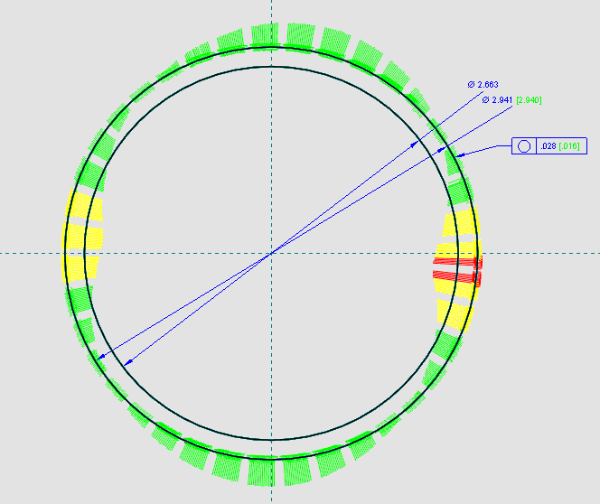
So Im trying to understand circularity and I thought I had a grasp on it until I see how some of my parts are measuring up in this metrology software. The picture shows a ring with a certain diameter and the only tolerance on there is the .035 circularity tolerance. The reading shows up at .016. The software is setup to show yellow lines when the tolerance is 75% or over. So the reading of .016 isnt even half of the tolerance. The reading at the point of yellow is about .010 off nominal. Does anyone understand how this could be showing up as yellow?

oor_bgmqpu.gif
 
Replies continue below

Recommended for you

You have deviations on both sides of the perfect circle. So you can only have +/-.0175 deviation. -.016 is more than 75% of that.

----------------------------------------

The Help for this program was created in Windows Help format, which depends on a feature that isn't included in this version of Windows.
 
Let me give this a shot.

The dimensions indicate the circles represent the size limits and NOT the circularity tolerance. I assume the green and yellow "bars" represent the radial distance of the surface relative to an axis of rotation (center of the inspection device). You did not provide the "thickness" of the part, so I assume it is "thin" -a disc and not a pin.

First: Rule #1 is in effect here, so the surface can never be outside the boundary of a perfect form at MMC - a circle of 2.941. Many of the green bars extend beyond the 2.941 circle, which represents the perfect boundary, so Rule #1 is violated and the size is too large and also out of tolerance.

Second: The .035 circularity tolerance reduces the default 2.941-2.663 = .278 circularity error allowed by Rule #1 to two coaxial circles .035 radially separated. These circles "float" inside the boundary of a perfect form circle of 2.941 and get larger or smaller as the size varies. Again, I assume the two circles you show are size limits and not the .035 form error circles, which would be much "smaller" at the magnification shown.

One way to inspect the part NOT using a CMM, which would "automate" the verification:

1) the actual local size (micrometer readings) at every cross-section must be within size limits
2) the part must fit through a ring gauge with an inside diameter of 2.941 to confirm the surface is not outside the boundary of a perfect form circle.
3) a series of see-through Mylars (to accommodate different part diameters) with two .035 apart circularity circles is made. One at a time they are overlayed over the plot of green bars. The Mylar can be shifted around - no datums here. One of the Mylars must "capture" all of the outside edges of the green bars inside the coaxial circles. This confirms the circularity error. This technique is not viable at low magnification.

Hope this helps


Certified Sr. GD&T Professional
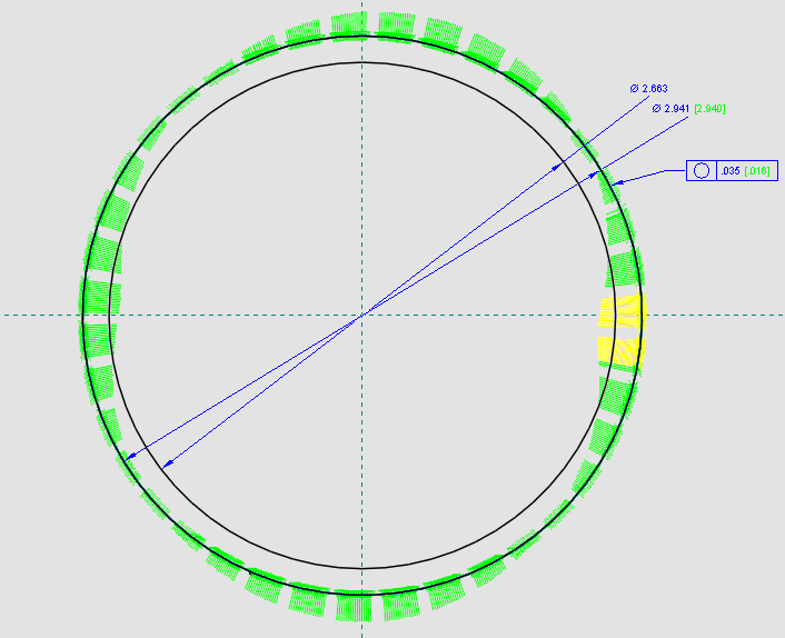
 
Let me clarify something that I did not before. The part I am measuring is a ring, it has an Outer Diameter and an Inner Diameter. I am only showing the measurement of the outer diameter of 2.941 and not the inner diameter of 2.663 both of which are nominal dimensions. I probably should have deleted the inner diameter from the test to not confuse anybody. Sorry >.<

Isnt the .016 measurement a combination of the high side and the low side? In this case, the circle is off perfect +.006 and -.010 which I can see makes the .016 reading. This software would change the actual reading dimension to show up yellow also if it was getting out of tolerance. So the .016 would show up in yellow as well as the area that is getting out of tolerance. I tested when the reading shows as a fail and it fails when the Circularity is toleranced at .028 but passes when its at .029 so I dont see how the .016 reading Im getting follows that reasoning because then it would fail once it got lower than .032.

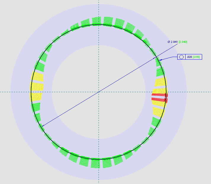
oor2_ipukas.gif
 
Here is the same example as above without the ID and with the boundary limits shown set by the .028 Circularity tolerance I altered it to.
oor3_czvn6i.gif
 
I am confused.

What is the ".016 reading"?

What is the blue annular "ring"?

Why did the .035 change to .028?

Certified Sr. GD&T Professional
 
I suggest contacting the software provider for the documentation.

Also, the software guys are jerks. Pale green on pale blue is tough to read.
 
mkcski itst all explained in my previous posts.

The .016 is the results of the measured data, its the circularity reading.
The blue ring is the tolerance limits set by .028 circularity test. So +/- .014 on each side of that test.
The the .035 changed because I wanted to find out when the software resulted in a fail. So .028 is when this data first failed.

What I am confused about is that I thought the data would fail once the measured data went beyond the blue tolerance boundaries. But its failing before that point so Im trying to find out if theres something about circularity that Im not understanding. The measured data is only .010 max off nominal on any side.
 
How can the software give circularity error reading = .016, yet in the same report that this number fails circularity tolerance of .028?

I agree with 3DDave, contacting the softwate provider is definitely a thing to do.
 
do you use the software to analyse the dimension? or you use the software to check the part?
 
Pmarc, that is what I'm trying to figure out. I was unsure if theres some underlying mechanics about circularity that I dont understand that are causing this data to fail earlier than I would think.
 
Vindicit:

Now I know why I was confused. The software itself is confusing. I am used to FARO reporting, which is much more intuitive (assuming you know what Circularity is). So...I agree with the others. The software engineers do not understand what Circularity is and how to visually report in for ease of comprehension. Time to contact tech support.

Certified Sr. GD&T Professional
 
The circularity error is not a +/- value from a nominal value. I think that's why it's failing as soon as you reach .014 from nominal. The error is the distance between the farthest out and farthest in point, unassociated with a dimension.

John Acosta, GDTP Senior Level
Manufacturing Engineering Tech
 
I agree with powerhound and with these clarifications. First: The axis of actual form error circles MUST be coaxial - on the same axis. The outer,largest circle of the actual error passes through the outer point (that is farthest from the common axis of the circles) and inner smallest circle passes through the inner point. Additionally, the distance between the two circles is the actual Circularity error. Second: This is a radial deviation so the actual local size (diameter) can be up to twice the form error.

Certified Sr. GD&T Professional
 
Is this just saying what I'm saying except with some elaboration on details? I'm asking because none of your post is saying anything different than what I said, you just went into more detail.

Regarding your second point, that warrants more explanation. I don't think I'm understanding you correctly.

John Acosta, GDTP Senior Level
Manufacturing Engineering Tech
 
powerhound:

Yes, I was just expanding on you statement. I am not sure how much Vindicit knows about the intricacies of Circularity error.

Second: those unfamiliar with circularity control assume you can use a mic-check to inspect circularity error. Diametrical error equals form error - not the case. The diameter (size)can vary twice the specified form tolerance and still have acceptable form error.

Certified Sr. GD&T Professional
 
Status
Not open for further replies.

Part and Inventory Search

Sponsor