Continue to Site

Eng-Tips is the largest engineering community on the Internet

Intelligent Work Forums for Engineering Professionals

  • Congratulations GregLocock on being selected by the Eng-Tips community for having the most helpful posts in the forums last week. Way to Go!

Could anyone help me with a material strenght calculation of this operating horn from crashed plane? 10

Status
Not open for further replies.

RedSnake

Electrical
Nov 7, 2020
10,828
Picture elevator to the left and stabilizer to the right.
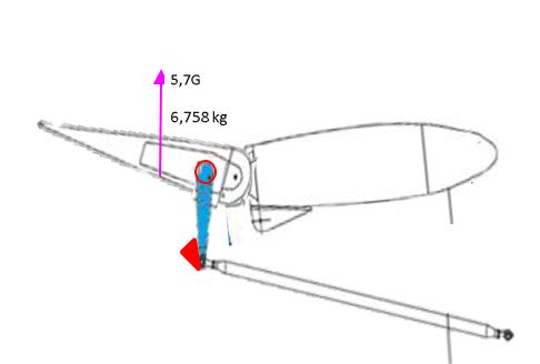
STABH1_pqq4vz.jpg

The red cirkel is a tourque tube on the rudder and have a diameter of 38 mm and the thickness is 1 mm.
The operating horn was a welded box design using steel sheet AISI 4130 in condition N thickness is 1 mm welded against the tourque tube.
On the uperside and sides (3/4 of the circumference) has 30% of the normal materiels strenght(severe lack of fusion).
The last 1/4 can be brittle or have been sheared.
The red triangle is the mechanical stop maximum up.
The relationship between hinge, tourquetube and elevetor edge ca..
0 --------1 --------------------7
Can this construction hold for 5,7 G ???


[img [URL unfurl="true"]https://res.cloudinary.com/engineering-com/image/upload/v1604784211/tips/STABH2_lpxbcz.jpg[/URL]


Properties Metric Imperial
Tensile strength, ultimate 560 MPa 81200 psi
Tensile strength, yield 460 MPa 66700 psi
Modulus of elasticity 190-210 GPa 27557-30458 ksi
Bulk modulus (Typical for steel) 140 GPa 20300 ksi
Shear modulus (Typical for steel) 80 GPa 11600 ksi
Poissons ratio 0.27-0.30 0.27-0.30
 
Replies continue below

Recommended for you

yep a command and control issue which is why the Chief pilot at Edsel was an utter anal retentive swearing domineering alpha male who took absolutely zero excuses from either the pilots or the meat bombs. If anyone got backlisted then that was it for life. No discussions no debate and any interaction was met by f off. Some would say harsh some would say no CRM, some would say absolutely zero customer focus... I would say 20 years safe operation and nothing unreasonable that i have heard about.... fine by me mate I would fly for you. He did actually ask me when I had 1200 hours but by that point I was multi crew. His limitation was min 1000hours and refused point blank to go any lower for jump pilots unless they had 45 drops themselves.
 
I do not get this!
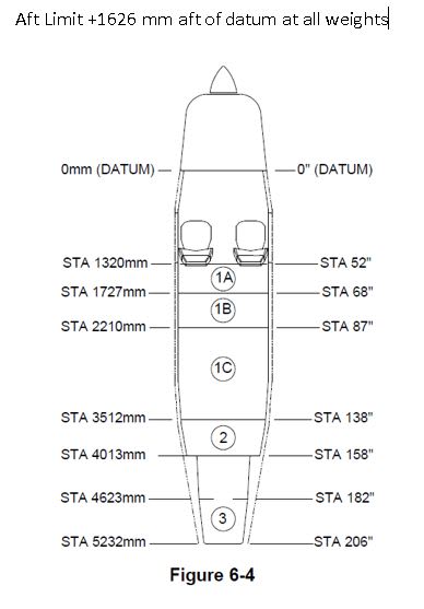
If the Forward Limit is +1219 mm aft of datum at 1089 kg or less
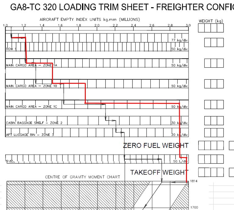
and I look at the chart from the manual it would not be possible to fly the plane with only the pilot if the person did not weigh at least 160 kg?!?!?
And the chart starts at around 1059 mm and adds 160 kg up to ca 1219 mm.

And in SHK's yellow graph they have started with about + 80 kg in 1219 mm I guess it is the pilot.

And have the planes basic weight was 1051.7 kg anything to do with it?

Please explain, I do not understand :-(

/A
 
its quite normal to have to put ballast in the boot when your flying things empty.

We had to put 150kg in the rear hold on the Q400 if we were empty even with a bar and cabin crew in the back. If it was an empty completely aircraft it was 350kg in the rear hold.

This mass and balance stuff is utterly critical its like the aircraft is sitting on an upside-down cup and if you get it wrong it falls off the side.
 
Outside forward isn;t a huge issue it just means increased loads during flare and makes it more positively stable. Outside the rear limits and everything becomes very twitchy and the aircraft won't naturally come back to a neutral stable point. Technical term negative stability.
 
But I think you can start seeing the issue now with the mass and balance and can see why the investigators are focusing as the primary cause. It really is exceptionally way out of limits.
 
I have before but the problem is that the chart only goes to 1814 kg and the plane can be loaded 1905 kg ?!
And I could not figur out how SHK made there balance sheet.. they tried to explain but when you compair the 2 it's just confusing.
If they hade presented it as a seesaw, it would have been easy :)
I probably did not understand because there is no stated counterweight.

datu_mrlfee.jpg
 
Okej pilot less den 160 kg
1A 2x90 kg, 2A 2x90 kg , 3A 4x90 kg , 60 L fuel
Correct or ???
I don't get this ??
Forward Limit +1219 mm aft of datum at 1089 kg or less
+1448 mm aft of datum at 1905 kg
Variation is linear between 1089 kg and 1905 kg.
Aft Limit +1626 mm aft of datum at all weights
The plane was made for 1905 kg but the chart only goes to 1814 kg (a not rebuilt plane)

diagram_qotzhb.jpg
 
60 ltrs of fuel is very low a lycombing burns about 80 ltrs an hour, minimum they should have had 100kg on onboard but the specific gravity for petrol is 0.72 ish so 140 ltrs

It could be that on paper the plane was in or not as far out as measured. Which is why they went to the effort of loading a similar aircraft up with a real load and then measuring it in real life. Maybe they all sit 500mm further back than the load sheet zones due the back pack.

Also every aircraft has its own dry weight and starting index they tend to get fatter with age. people will stick a box of oil in the rear hold a tow bar and other bits that they think that's light it won't matter but it all adds up.

The seesaw picture is a good one I tend to use sat on an upside down tea cup because I think in 3D of roll as well as pitch . The counter weight is the elevator lift which is variable through the pitch control. As its through the lift equation its effectiveness is V sqrt in relation to speed. 90% of nose down trim is quiet a lot on a clean aircraft. You need to trim forward when you put the flaps out for landing. They would have had issues if the drop had been cancelled.

But going back to your initial question about the arm/horn actuator if the plane was only used in this regime then it would have had a higher loading on the SN curve than a none para aircraft. But yet there was no sign of any fatigue failure surfaces.
 
The planes basic weight 1051.7 kg was the actual weight measured by SHK.
They calculated the weight to 1905 kg when the plane went down.
Which means that for total weight you have 853.3 kg left for people and fuel.

They gave me the numbers on the phone once, the plane, people and fuel but I forgot to write them down. But the plane's weight is ok.

One problem is that there is no proper mass and balance chart for skydiving.

This is from the report.

The Accident Investigation Board has consulted the type certificate holder's documents C99-52-01 and C16-99-42 which were used to demonstrate compliance with the requirements of EASA document SC-O23-div-01. With regard to the requirements for an examination of mass and mass center change during and after take-off, these are met according to the type certificate holder's documentation by video demonstration of a flight test and operational experience of the aircraft.
During the flight test, five jumpers, with a total weight of 500 kg, gathered at the door and carried out a coordinated jump of 8,000 feet. At the time, there were two pilots on board with a total weight of 186 kg. The speed at the exit was 80 knots. It was noted that the aircraft was controllable and that there were no problems with handling the aircraft. However, some balance sheet calculations have not been reported.

In this example 1905-1051,7 = 853,3.. 853,3- 686 = 167,3 kg for fuel, of course, the weight distribution is different here.

More from the report.

In accordance with the type certificate, there is a supplement to the flight manual for skydiving activities (C01-01-01). The purpose of the supplement is to provide the pilot with information on additional restrictions and special conditions as well as normal procedures and emergency procedures for parachuting.
The supplement states that there are no restrictions on the number of jumpers as long as the mass and balance are in accordance with the restrictions
Under the heading normal procedures, e.g. that it is necessary that the jumper receives a sufficient review of certain specified issues and that these are passed on to the parachutists.
The information includes i.a. how the cabin door opens during flight,
that the parachutists should be evenly distributed in the cabin area during take off and ascent,
that the parachutists should not gather at the exit for too long periods before jumping and that the target speed for out jumps is 80 knots.
In the supplement's section for mass and balance, it is stated e.g. following.
The maximum number of parachutists that may be transported is determined by the payload available for each given flight.
The total mass of the parachutists must not exceed this value.
To keep the aircraft within the limits of the mass center, the simplest method is to distribute the total number of parachutists evenly on the floor surface of the cabin.
When carrying out coordinated exits, a maximum of five (5) parachutists may gather behind the front edge of the cabin door exit with a maximum of three outside the aircraft.
The time to prepare such an arrangement should be as short as possible.
Parachutists inside the cabin should be as far forward as practically possible.

/A
 
redsnake said:
One problem is that there is no proper mass and balance chart for skydiving.

That's it in nutshell. Lack of oversight and control.

If you take 90kg out the front and put it in zone 1c the picture changes.

To note at work we have a whole department who's job it is to deal with mass and balance. Then as crew we check it and then the A220 fms does a check as well. We can also use manual load sheets similar to the one above to work it out but they are more restrictive than a load control loadsheet. Every bag is barcoded into the hold and the cabin crew do a seating check for blocks of 8 seats all down the cabin. The A220 because its new and not a stretched grandfathered design is relatively insensitive to being loaded. The Q400 which is a 4 times stretched model was a bit of a nightmare and people did have to get moved round the cabin to get it into the envelope. A 500kg lump of mail in the boot was always a pleasure to see. Which did cause arguments because pax tend to want to sit at the front and when the aircraft only has 10 people on board and no cargo we needed them behind the wings to get into the envelope.

After a flight has taken place its audited in house and then every so often there is a local CAA audit which then pulls a certain % of flights. And then every 2-3 years there is an EASA exchange audit between CAA's which does the same thing. And they do pull things up! one of the guys got pulled for landing 20 kg over weight. Which realistically is absolutely nothing and the fuel gauges aren't accurate to 20 kg. But an over weight landing inspection was completed and he had to revise the aircraft limitations and sit an exam and was suspended for 2 days until that was complete which he lost some money over. The daft thing is if he had realise it at the time and written a report about it and the reason for doing it then nothing would have been said about it.
 
When it comes to visualising the impact of an aft cg, I find the most helpful image is one of trying to throw a dart flights-first. It's not just about the absolute location of the cg - it's where it is relative to the centre of pressure.

A.
 
I was running some calcs using scaffolding limitations for allowable torque on a tube.

Seems to me 2cm weld each side of the tube would be good for 1.5 meter lever with 500kg off it with box section.
 
I think the arm is not your issue.

It was only designed to work in one plane. Might have been better not to weld the other surfaces but the root causes lie elsewhere.

Out of CoG envelope and hypoxia is my take on key issues in this tragic incident. I refuse to call these "accidents" any more because they weren't accidental, they could have been prevented.

Skydivers like doors on aircraft because it gets bloody cold at altitude but maybe they shouldn't be allowed to be closed. At least some would get out if it all goes seriously wrong.

Remember - More details = better answers
Also: If you get a response it's polite to respond to it.
 
I agree but the original question was about the strength of a box section welded onto a tube to be used a torque drive. From my calcs the push rod should fail before the arm with 2cm of perfect weld on the tube at 90 degree in tension. Pushing which is not the case here is basically shear of the tube v buckling of a square section. Take your pick but they are collosal.

The end cap covering I presume is to stop moisture getting in the end of the tube.

There has been a fatality in Inverness with an auto gyro. The rotor came off. Don't know the student have zero clue bout auto gyros. Two changes of owner since I was on there books and 9.5 years... It crashed in one of the fishery patrol pilots farms. Thankfully he did the necessary.
 
Btw I reckon Anna should be allowed to post what ever she like question wise.

If she feels comfortable doing it with us.

Gland bolts are called different things across flavours of engineering. Petroleum will call them flange bolts trapping a spiral. They basically trap a seal between two plates and squish it onto something to create a seal. The marine lot call them something else. It's a bit of a swine what to put into search engines. Once you realise there is 10 names for the same thing it's easier. If the thing is rotating it's different set of calcs
 
I received the full metal survey report today.
On the left elevator, the push rod had come off.
I know the left side elevator broke off last, so it has nothing to do with the cause but I think the right side should have withstood more.

/ Anna

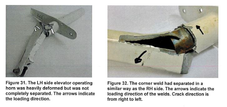
4.3.6 Examination of the Elevator operating horn LH side
The LH elevator operating horn had failed but was not completely separated. Longitudinal
cracks followed the corner weld fusion zone. The weld quality of the operating horn is
sim ilar to that of the RH operating horn and does not fulfil normal weld quality
requirements. The lack of fusion has guided the crack path along the corner weld.
Left_sida_chreqn.jpg

4.4 Examination of the broken Elevator Eye Bolt
The eye balt push rod connected to the LH elevator horn was braken as can be seen in fig 33.The push rod showed a sharp 23° bend 135 mm from the fractured eye balt.

The fracture showed an overload fracture starting in the bottom of the threads at the
location of same damaged threads. The starting area and the fracture direction are marked in Figure 35.
Push_rod_t93qka.jpg

The fracture showed an overload fracture starting in the bottom of the threads at the
location of same damaged threads. The starting area and the fracture direction are marked in Figure 35.
 
It looks like a lateral material tearing failure mode. Not in a design load plane.

I am a bit scared of ridicule giving hard numbers here.

The bolt on the U swivel is from what can tell is 6mmm. The rod is about 1.2 X it's failure limit. The box section arm.. many times more than that. And a I think I have screwed up the calcs amount of weld between box and tube it's so little.

The welding I fully agree is a tertiary factor which should be mentioned in the report.

Btw that's what I expected to see for the rod failure. It's unfortunately a normal failure mode

 
I also asked for more measurements. The length of the elevator and the length between the hinge and the lever.

But they say they do not have them!?!
But he thought that the drawings with the main dimensions were scalable so it is possible to calculate on an approximate.

I have also asked how good the hinges between the stabilizer and the elevator were, but they can not answer that, only that they were lubricated 70 hours ago.

It has a fairly long lever, but I do not know how much play is needed there to get a break in the lever

But he wrote the following, but I do not understand what it is :-(

• The rudder has a Mean Geomatric Cord of 20.7898 inches (inch)

The only calculation they made on the right elevator lever is the one I posted earlier.

The operating horn was a welded box design using steel sheet AISI 4130 in condition N. The design of the operating arm was based on two 90° bent sheet meta! pieces welded together using two longitudinal corner welds. The operating horn was welded to a tube mounted in the elevator.

Flange cross section = 23x 1 = 23 mm2
Yield strength 4130 = 50 daN / mm2
Flange breaking load (F2) = 23x50 = 1 150daN
Moment = 1150x38 = 43 700 daNmm
F1 = 43 700/127 = 344daN
Gear ratio for the steering wheel approximately 5: 1
Steering wheel power = 344/5 = 68.8 daN for breakage
(Assuming that the entire steering wheel power goes only to the right elevetor.
In addition, material is added in area A
The lever has thus had good strength despite the welding error.


/A
 
Chord is the aerofoil characteristic.

Go for weakest link which is that bolt that goes thought the U bracket on the end of the arm. When you see what it can take as well as the rod. You can see why with the lack of fatigue surfaces in the other area they have discounted that failure tree and put it down to inflght breakup due exceeding limitations
 
Status
Not open for further replies.

Part and Inventory Search

Sponsor