Eng-Tips is the largest engineering community on the Internet

Intelligent Work Forums for Engineering Professionals

Datum Targets in MBD 1

Status
Not open for further replies.

Mech1595

Mechanical
Oct 16, 2023
29
0
1
US
All,

Had an interesting one related to Datum Targets come through recently, and was hoping you could provide some insight.
Below is a simplified example of the component. The customer has Datum A defined with (3) Datum Target Points: A1, A2, A3.
They also have Parallelism to [A] specified on the yellow surface.

Here's where I'm lost:
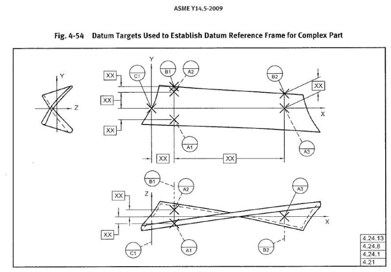
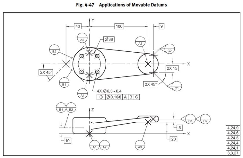
Their design intent is for Datum Plane A to be parallel to the yellow surface, but I don't understand how it could be with this info. I looked through Y14.5-2009 and found Fig 4-47 as an example, but they have the Datum A targets offset with the Basic [20]. This component is defined with MBD, with no basic offset like Fig. 4-47, just WCS coordinates for the Datum Targets.
It's also located way out in vehicle position, and not aligned to the WCS in a way that any of the planes (XY, XZ, YZ) would match intended Datum Plane A orientation.
Is this valid? If so, what is the mechanism driving Datum A to be oriented as they suggest? Would Datum A not just be coincident with the (3) Datum Target Points?
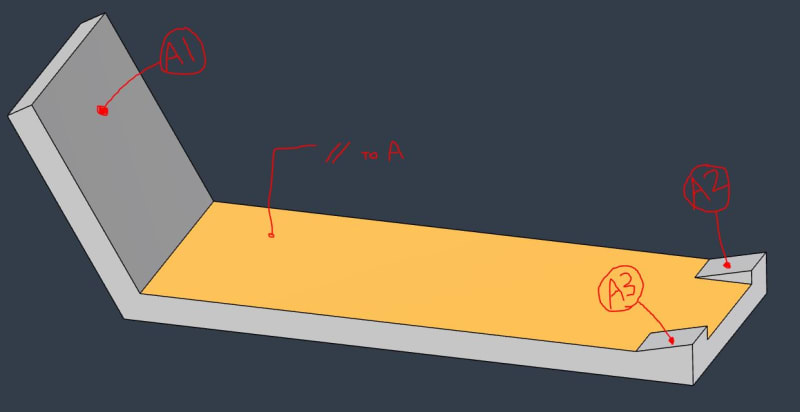
Datum_Targets_jltvd3.jpg


4-47_woagwx.jpg
 
Replies continue below

Recommended for you

Datum targets do not generate datum planes. Even if they are coplanar, there isn't a datum plane to be parallel to, unless the target is only a limited area of a plane or a limited area of a cylinder that can have a related axis.

Your example is neither of those cases.

Since this is a generalized orientation control via the datum targets, the generalized orientation control to use is angularity. You can determine/make explicit the nominal/basic angle for that surface relative to the datum targets.

 
3DDave,

Not sure I understand, if the targets aren't making a plane, how can I control angularity of a surface to the targets?


3DDave said:
Datum targets do not generate datum planes.
3DDave said:
the generalized orientation control to use is angularity. You can determine/make explicit the nominal/basic angle for that surface relative to the datum targets.
 
In the MBD the plane being controlled has a basic orientation, per MBD definition**, as do the features of the datum target surfaces.

**Edit: well that seems redundant, but I'm referring to the definitions of how MBD is conducted.
***Edit 2: to clarify which plane has the basic orientation
 
Chris,

The individual datum targets? No. They don't need to be parallel. They need to have identifiable extent and location and orientation, all of which are part of the model.
 
Your datum plane should be coincident with at least one datum target point with a dimension to each of the remaining target points.
[edit]Depending on how you need the plane orientation will determine the dimensional orientation between target points.[/edit]

"Know the rules well, so you can break them effectively."
-Dalai Lama XIV
 
in the OPs example, the plane could go through points A2 and A3 with a dimension to A1 controlling the angle of the plane relative to the part.
You could also base the plane on point A1 and dimension to points A2 and A3.
What is missing from the figure taken from Y14.5 is the datum plane identification, which was not the subject of the figure so was not necessary for its purpose.
You get to define what you require.

"Know the rules well, so you can break them effectively."
-Dalai Lama XIV
 
A useful practice when defining datum features using datum targets is to link the datum targets to a coordinate system, by implied or explicit basic dimensions *. While not always required, it is often a practical solution.

For example, in several examples in the standard, datum targets are connected to a coordinate system (CSYS), like in example 4-47, where datum targets A1 and A2 are on a CSYS plane.

Those coordinate systems represent the datum reference frame so it is highly related to how the tolerance zones for locating and orienting geometric tolerances are defined.

In MBD, this is especially relevant because every datum reference frame must be associated to a coordinate system. Some software allows for the automatic creation of a coordinate system to represent a defined datum reference frame.

* In MBD, basic dimensions do not always need to be displayed, as all distances and angles in the model can be interpreted as BASIC when applicable.
 
I would push back. I don't think the current methodology is proper or functional. My recommendation would be to move datum A to the yellow plane surface, and apply a profile tolerance of the 3 current angled surfaces back to A (and B and C). Then the current A datum can be reassigned as Datum D and everything else can be controlled back to D-B-C.

Best regards,
Doug Hunter
Altarium Technical Consulting
 
3DDave said:
In the MBD the plane being controlled has a basic orientation, per MBD definition**, as do the features of the datum target surfaces.
Ahhh okay, that makes sense.

Doug Hunter said:
My recommendation would be to move datum A to the yellow plane surface, and apply a profile tolerance of the 3 current angled surfaces back to A (and B and C).
Interesting. Is the idea behind this just to separately qualify the faces that the Datum Targets are located with respect to the yellow surface, and use D-B-C to control location/orientation of the remaining features? Just for more info, the yellow plane surface does not contact a mating component in the assembly, but orientation is important for optical performance.

drawoh said:
Is there a dimension to locate datum target A1?
All three Datum Targets are just located with coordinates, no specified dimensions between the targets like shown in Fig 4-47 above.
 
drawoh said:
Is there a dimension to locate datum target A1?

Do you need one or you just supposed to "measured" it from the 3D CAD model and consider it basic or TED.
Or if A1 is primary then you locate (again basic) other features or datum targets FROM it.

I am learning MBD hence asking..............

 
Mech1595,

Essentially, yes. My thinking is that the angled surfaces are intended to be used for the inspection fixturing, so the control of everything should still go back to them, but they are not optimal for use as a primary datum, and the flat surface is optimal. At some point you may need to check the datum D surfaces back to something more fundamental, and this provides a means for defining them and checking them.

Best regards,
Doug Hunter
Altarium Technical Consulting
 
Surfaces chosen for datum references mainly should be the ones that locate and orient the item in use. Functional datum feature selections are the optimal choice, though sometimes the design itself is not the most optimal.
 
greenimi said:
Do you need one or you just supposed to "measured" it from the 3D CAD model and consider it basic or TED. Or if A1 is primary then you locate (again basic) other features or datum targets FROM it.

Try to design your fixture. The three datum targets are implemented by spherical topped pins which contact the surfaces at the points (not) specified. On a small surface, I will aim for the middle. Consider that the original question was whether or not a given face could be parallel to Datum[ ]A. The orientation of datum "surface"[ ]A is controlled by the exact postion of datum target[ ]A1. This matters.

--
JHG
 
The terminating dot indicates the surface is a datum target area. The section lines would not be required for MBD as selecting the datum target indicator is supposed to highlight the applicable area.
 
Target points are mentioned at least twice in the original post.

In my opinion, the terminating dots in the original illustration mean as little as the fact that the circular symbols used in that illustration are not datum target symbols at all.

Besides, if the entire surface, and not just portion of it, is used to establish a datum, then I don't think it should be a datum target application in the first place.
 
Status
Not open for further replies.
Back
Top