Continue to Site

Eng-Tips is the largest engineering community on the Internet

Intelligent Work Forums for Engineering Professionals

  • Congratulations cowski on being selected by the Eng-Tips community for having the most helpful posts in the forums last week. Way to Go!

Feature Of Size definition

Status
Not open for further replies.

Sem_D220

Mechanical
Jul 9, 2018
290
My first question is - according to ASME Y14.5 2009, how would you classify the cylindrical interrupted surface of diameter 55 and the width 52 in the following sketch?
Are they:
- Regular features of size (with interruptions)?
- Irregular features of size type A? (Or maybe even B?)
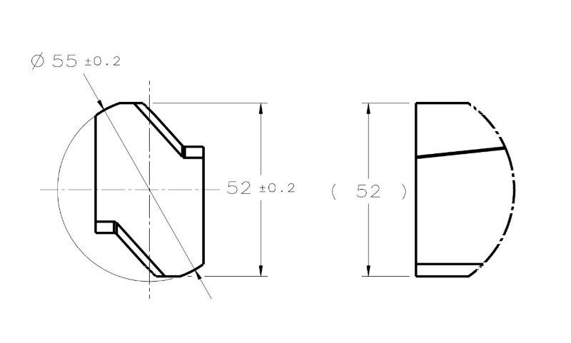
FOS_QUESTION_aejzhn.jpg


My second question is for those who have access to the 2018 standard:
What is the change that was introduced to the concept of feature of size?
I read that there was a change in the concept in the announcement at the ASME website which pmarc linked to in the thread about the new standard.
 
Replies continue below

Recommended for you

Sem_D220 said:
I take the line "Sorry, but that is all I can offer" as a sign that you grow tired of this discourse.

That line was just my frank admission that I really failed in this thread - I failed because I wasn't able to convince you that you have been wrong. 

I read your reply to chez311 (after I submitted my comment), but my only reaction to it can be that in the example with rotating vise your thought process is imply incorrect. As pylfrm explained, once the 19.42 envelope gets in contact with the feature at the top-left, top-right, and bottom-left points, further contraction will be impossible, unless you expand the envelope and rotate it relative to the feature. 

To me, the way you have been explaining how further contraction towards 19 and below would be possible is a description of a deliberate action leading to contraction of the envelope about other feature than the feature it should be and could be contracted about. It is like saying that for perfectly manufactured block 20 mm high and for example of 5 mm wide the UAME of the height is 5 mm. This is the path your argument follows, and I truly believe it is a wrong path. 

Just in case if you are going to say that the same action is taken in the non-opposed feature example, my answer is that this is not true. In the non-opposed feature case, no matter how hard one tries to precisely contract the envelope about the considered feature, the lack of opposed points will let the envelope to contract further and further. In your example of '19 or less' envelope, one has to first try hard not to contact the considered feature in the intended way to be able to contract the envelope towards 19 and below.
 
pylfrm,

Thank you for your input and the images. I think they objectively (mathematically) explain what chez311 and I have been trying to explain with words throughout the course of this discussion.

The only thing I would add is that the geometry in image 3 is a classic example of a "rocker", and just like in case of convex (nominally planar) datum surface, where a candidate datum concept would be involved (in prior-to-Y14.5-2018 era), the same idea can be applied here. There is a set of candidate unrelated actual mating envelopes, but that doesn't mean the concept of the UAME itself is invalid.
 
pmarc said:
To me, the way you have been explaining how further contraction towards 19 and below would be possible is a description of a deliberate action leading to contraction of the envelope about other feature than the feature it should be and could be contracted about.

This would not be a deliberate action but the result of relying solely on "physical reality" that suggests that any opposed feature of size will constrain it's actual mating envelope and that the contraction of the envelope will have to be stopped by the feature itself.

Edit: I rechecked the simulstor behavior, no expansion in the process.
 
Feel free to call it as you want. All I am saying is that your process of establishing the '19 or less' envelope is not correct and unavoidably leads to weird conclusions like the one I suggested with the rectangular block 20 mm high X 5 mm wide.
 
I never said it was a correct process, and you are right about the weird conclusions that it leads to.
This is what I was trying to say and show all along. Unlike I was told in the beginning of this thread - you can't take "maximum possible contact" out of the UAME concept, not even for regular opposed features of size.
 
Sem_D220 said:
Unlike I was told in the beginning of this thread - you can't take "maximum possible contact" out of the UAME concept, not even for regular opposed features of size.
Are you just starting over?
 
I have no idea what is the reason or the purpose of you asking this and what am I supposed to answer.

Regarding the quote in your response - you stated yourself that 3 points of contact are needed for correct UAME simulation. So you are not even supposed to disagree with this.
 
You didn't have to answer. We apparently disagree with each other and that doesn't seem like going to change. Either it's because we don't understand or don't want to understand each other.

Anyway, I am afraid I will not be able to change it. Thank you.
 
I re-read your statement that I quoted and I agree with it.
 
Apparently we don't always disagree. Anyhow, thank you too.
 
Sem D220 18 Mar 19 22:06 said:
Unless you use excessive force, the object you are inspecting will not translate or rotate in the directions at which the constrained degrees of freedom prevent movement. This is why I brought up the DRF as a subject for consideration after it was stated that for unopposed features, the simulation process will result in movement (rotation) of the part and inability to simulate the UAME as a result of that movement.
I've already stated previously I do not believe the frame of reference matters - part vs. boundary rotating/translating is inconsequential the end result should be the same - the UAME should not be constrained to any DRF. A good gauging setup should be able to handle this (albeit possibly expensive/complex or not feasible for certain cases) - a CMM certainly can.

pmarc 19 Mar 19 11:25 said:
To me, the way you have been explaining how further contraction towards 19 and below would be possible is a description of a deliberate action leading to contraction of the envelope about other feature than the feature it should be and could be contracted about. It is like saying that for perfectly manufactured block 20 mm high and for example of 5 mm wide the UAME of the height is 5 mm. This is the path your argument follows, and I truly believe it is a wrong path.
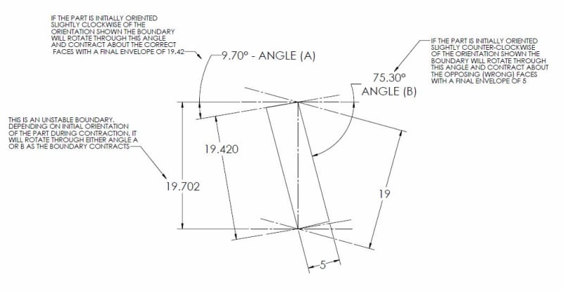
I agree with pmarc's statement. See my figure below - depending on the initial orientation of the part in relation to the boundary/simulator during contraction it will either end up at a final boundary of 19.42 on the faces/feature of interest (correct) or of 5 on the opposing faces (wrong). There is no situation where the feature as you have shown it will start in the correct orientation, rotate/contract through angle A all the way to the 19.42 boundary and then continue to rotate/contract to anything less than that. It seems pmarc was unable to convince you of this and if that is the case I doubt my below figure will be enough to do so.

I can however envision a situation where a similar shape would create a situation which you describe. This, I think even more than the convex/barrel shape, will require excessive size/form and possibly orientation error.

FOS_-_straight_unstable_l9niiy.jpg
 
Sem D220 18 Mar 19 22:06 said:
As I said several times, the DRF constrains the degrees of freedom of the part/feature, but not of the UAME.

I should clarify that I absolutely have been aware you have been saying this several times. It is the fact that each time you have proceeded to follow it with statements that in my mind, and I think others - though I will not speak for them, contradicts that conclusion which I think bothers me. The difference is that for me the definition ends there - the UAME is not constrained or defined relative to any DRF. Period. No further clarification is necessary - the fact that it is "not constrained to any datum(s)" per 1.3.25.1 means no datums are involved, directly or indirectly.
 
chez311 said:
I've already stated previously I do not believe the frame of reference matters - part vs. boundary rotating/translating is inconsequential the end result should be the same
I have also said that essentially one can view the rotation of the UAME relative to the part as rotation of the part relative to the UAME. Physically they are the same. But, I always imagine geometrical controls in association with the fixture and inspection process. If the part is constrained in a fixture while the UAME simulated as it would be for the part from fig. 7-65 I posted above, and someone mentions that the UAME (not the RAME, as I hope you now realize) simulator for the slot may move or rotate the part during the interaction (the analogy to that is your sentence "as the boundary closes down the feature will rotate as that boundary closes in" from 8 Mar 19 14:33 ) , I think it is natural to respond by mentioning that the part is constrained in movement by the datum feature simulators A and B (Not by the DRF as I initially described - thank you pylfrm for the correction), and therefore the part can't move. If a ball bounces from the wall I will not say that the wall bounces from the ball. Even though physically speaking the frame of reference doesn't matter in this case too, I say the ball bounces from the wall because the wall is fixed in place and the ball is not. That is the natural way to look at things (at least for me).

If you looked at the figure I posted at 19 Mar 19 10:07 you could see my explanation on how further contraction below 19.42 is possible. I can describe it for the figure you posted: the exact behavior probably depends on the exact as produced angles and there could probably be various scenarios, but if your part dictates a similar UAME simulator behavior, after reaching dimension 19.42, if the "manual" contraction doesn't stop deliberately by the "operator" at exactly that moment, the pivot point around which the top plane of the simulator rotates will translate from the top right corner to the top left corner of the part, while the pivot point around which the bottom plane of the simulator rotates will remain the bottom left corner. This situation allows for a smooth transition and continuous contraction below 19.42.

Edit: quote added in the beginning of the post
 
I hope this illustration will help to visualize how the UAME simulator for a regular opposed as produced FOS might fail if the contraction is not stopped deliberately when maximum contact is achieved. Notice that the UAME envelope will not have to expand and then contracted again at any step to behave as shown.

Correct me if I'm wrong, but I'm going to guess that your example shape is a polygon with vertices at the following coordinates (listed counterclockwise from top right):

p1 = (5, 20 - 5 * tan(7°))
p2 = (0, 20)
p3 = (0, 5 * tan(5°))
p4 = (5, 0)

Between step 2 (19.42 envelope width) and step 3 (19.00 envelope width) in your latest illustration, the envelope must rotate through an orientation where points p1 and p3 are directly opposed. The distance between these points is sqrt(5^2 + (20 - 5 * tan(7°) - 5 * tan(5°))^2) = 19.597212, so the envelope must indeed expand to allow this.

I ran this geometry through my plot-generating program. Image 4 is the result. A discontinuity in the slope is evident at a rotation angle of 5° and an envelope width of 19.49, corresponding to your step 1. Envelope width reaches a local minimum of 19.42 at a rotation angle of 7°, corresponding to your step 2. Getting from there to your step 3 requires going back up and over a local maximum.

What are we missing here?


The only thing I would add is that the geometry in image 3 is a classic example of a "rocker", and just like in case of convex (nominally planar) datum surface, where a candidate datum concept would be involved (in prior-to-Y14.5-2018 era), the same idea can be applied here. There is a set of candidate unrelated actual mating envelopes, but that doesn't mean the concept of the UAME itself is invalid.

Could you expand on how this candidate UAME concept might be applied, specifically to the geometry in my image 3? I'm particularly interested in what rule might be used to determine what is considered a valid candidate.


pylfrm
 
Thank you pylfrm for performing the check. I didn't notice the local maximum that is expected between step 2 and 3. * In case you still have the data saved, could you change the shape to a parallelogram ( two 5° angles instead of a 5° and a 7° ) and check if a local maximum is expected in that case too?

pylfrm said:
What are we missing here?

What you (in plural) are missing is that this particular as produced polygon was only intended to serve as an example to communicate a valid point. With additional form deviation at the bottom left corner or a slightly different produced shape the UAME simulator could behave exactly as I showed. In addition, there are the convex "rockers" that don't have a solution, with which pmarc suggests to deal by a method that is intended to be applied on planar features and not features of size.

The point is: the fact that a feature was designed as a simple rectangular feature of size cannot guarantee the ability of the feature to physically restrict the contraction of the envelope simulator about it. And since it can't, the differentiation between features of size and none features of size cannot be based on that. Furthermore, the concept of a contracting envelope until being physically constrained and brought to an equilibrium of forces by the surfaces of the feature is not implied in any form by the definition of the unrelated actual envelope in the standard.

Edit: * never mind about the 5° parallelogram. I have seen that it behaves the same.
 
Sem D220 19 Mar 19 20:58 said:
But, I always imagine geometrical controls in association with the fixture and inspection process. If the part is constrained in a fixture while the UAME simulated as it would be for the part from fig. 7-65 I posted above, and someone mentions that the UAME (not the RAME, as I hope you now realize) simulator for the slot may move or rotate the part during the interaction (the analogy to that is your sentence "as the boundary closes down the feature will rotate as that boundary closes in" from 8 Mar 19 14:33 ) , I think it is natural to respond by mentioning that the part is constrained in movement by the datum feature simulators A and B (Not by the DRF as I initially described - thank you pylfrm for the correction), and therefore the part can't move.
This may be true in many instances, but not all - it depends on what is being simulated/inspected. There is no requirement that the part ALWAYS be constrained when simulating the UAME. If the desire is to check the UAME against the position tolerance zone then yes the part would have to be fixed relative to the applicable datum features to establish said tolerance zone. If the desire was to check only the size of the UAME for whatever reason there would be no similar requirement and could be perfectly feasible in some instances to have the part unconstrained - ie: for a small, lightweight part it could be held in your hand and a simulator fitted into/onto the applicable feature. I know that for practical purposes you might not want to literally hold it in your hand (thermal expansion from body heat - especially on a small part) but my point remains that there is no requirement to fix it to a specific datum feature(s) in that case and simulation could force the part to move or the part/simulator to move relative to each other.

Most importantly perhaps is the case of a primary datum feature. In that case the part would indeed be unconstrained relative to any other datum features and the simulator (UAME boundary) could be fixed. As the boundary contracts/expands into contact with the primary datum feature the part would be expected to move in relation to the simulator.

It is for these reasons which I stand by my assertion that the frame of reference does not matter - in certain cases the boundary/simulator will move, in others the part, or both. It depends on what is being simulated and/or what is feasible due to part/simulator size/weight/design.

Sem D220 20 Mar 19 04:32 said:
The point is: the fact that a feature was designed as a simple rectangular feature of size cannot guarantee the ability of the feature to physically restrict the contraction of the envelope simulator about it. And since it can't, the differentiation between features of size and none features of size cannot be based on that.
Perhaps not within every single possible variation or feature configuration (ie: high length/width ratios combined with loose tolerances as in your example) which might require special treatment (fitting routines, etc..) however for the vast majority of cases I would say it does. If what you say was true, standard workholding like a vise would be pretty useless as this is the very simple concept that it works on - contract until it stops. Just because there are a select few cases for which this doesn't work requiring some special treatment is not a reason to stop using a vise for the vast majority of cases where it does work. The same applies to the similar definition of a UAME.

Sem D220 20 Mar 19 04:32 said:
Furthermore, the concept of a contracting envelope until being physically constrained and brought to an equilibrium of forces by the surfaces of the feature is not implied in any form by the definition of the unrelated actual envelope in the standard.
I am of the opposing opinion - I would say it is the only definition directly supported by the standard. It is an unambiguous interpretation of the statement found in 1.3.25 stating an actual mating envelope is "A similar perfect feature(s) counterpart of smallest size that can be contracted about an external feature(s) or largest size that can be expanded within an internal feature(s)". A minimum/maximum of an envelope occurs when it has contracted/expanded to its fullest extent. Any inclusion of "maximum possible contact" adds no clarity as that term is not defined, in addition to not being in the original definition (your point taken about it being discussed in relation to primary datum references notwithstanding). Any discussion of "equilibrium of forces" is just the physical reality of simulating such a boundary.
 
Additionally, pylfrm's plots show that a minimum can be defined mathematically - no "equilibrium of forces" necessary, which would just be the result of bringing a physical simulator in contact with a physical feature.

pylfrm - thank you for those plots. I may derive a similar program if I have time. I was going to make a series of figures in CAD but your method may prove to be the simpler, as well as more convincing, one.
 
chez311,
Regarding the effect of datum feature simulators or lack of them on the interaction between features and UAME envelopes, I agree with the points you brought up. The most important thing is that it remains clear that relative movement problems can be dealt with by technical means and one shouldn't sort features to types according to the probability to experience relative movement problems; for a primary datum feature simulation, the simulator can be fixed, as you said. For position inspection, the part will be fixed during UAME simulation, as you acknowledged. If both the simulator and the part are held manually as in the additional scenario you mentioned, the hands act as the constraining device when needed. Relative movement can and will occur, but it also can and will be controlled.

chez311 said:
I am of the opposing opinion - I would say it is the only definition directly supported by the standard. It is an unambiguous interpretation of the statement found in 1.3.25 stating an actual mating envelope is "A similar perfect feature(s) counterpart of smallest size that can be contracted about an external feature(s) or largest size that can be expanded within an internal feature(s)".

You ended the quote in the middle of a sentence. The definition is not complete without the missing part: "... so that it coincides with the highest points". This is not just a clarification about the envelope being outside of the material, but part of the requirement: the simulator must surround the feature in a close contact relationship.

This essentially means that if an envelope that conforms to this condition can be found for a given as produced feature, this envelope is the UAME. If the envelope can contract further, but the further contraction is accompanied by loosening the contact with the feature, the envelope that was already established when there was a sufficient contact is still valid, as it remains the smallest envelope that conforms to the definition. There is nothing in the definition that says that it is mandatory that the physical contact between the feature and a simulator constrains the simulator as in a simple case of a vise that is stopped by the object it closes on.

This brings me to pylfrm's plots. It is not always the minimum value that should be looked for. Even where a local minima can't be detected, one of the values can represent the actual UAME size. The plot doesn't provide the information about the amount of contact along the process.

Inspection-wise, it is all a question of the available technology. If detection of the UAME which "coincides with the highest points" (according to pmarc, there should be 3 of them) is possible for a pair of "offset-opposed" surfaces, and nothing in the process contradicts the standard, why forbid it?
 
pylfrm said:
Could you expand on how this candidate UAME concept might be applied, specifically to the geometry in my image 3? I'm particularly interested in what rule might be used to determine what is considered a valid candidate.

This is just a quick idea:

I am not sure it could be applied to all kinds of rocking actual geometries of this type of regular feature of size, but I think that it could work for the geometry in image 3. Of course, it is not supported by any standard, as far as I can tell, but I would call it a derivative of the procedure of finding a valid candidate datum plane for primary planar datum feature, as defined in Y14.5.1.
 
Sem_D220,

You claim that the underlined portion of the following definition is important:

ASME Y14.5-2009 para. 1.3.25 said:
envelope, actual mating: this envelope is outside the material. A similar perfect feature(s) counterpart of smallest size that can be contracted about an external feature(s) or largest size that can be expanded within an internal feature(s) so that it coincides with the surface(s) at the highest points.

Can you describe what you think the portion in bold means? Please be as precise as you can.


pmarc,

Thank you for providing the explanation and illustrations.

I think the A = B condition might be problematic, especially for a less symmetrical case such as image 5. I'll have to give this some more thought though.


pylfrm
 
Status
Not open for further replies.

Part and Inventory Search

Sponsor