Continue to Site

Eng-Tips is the largest engineering community on the Internet

Intelligent Work Forums for Engineering Professionals

  • Congratulations waross on being selected by the Eng-Tips community for having the most helpful posts in the forums last week. Way to Go!

Fig. 6-15, para. 6.4.4 Y14.5-2009 1

Status
Not open for further replies.

Burunduk

Mechanical
May 2, 2019
2,361
6.4.4:
"There may be applications where the full additional tolerance allowable may not meet the functional requirements.
In such cases, the amount of additional tolerance may be limited by stating a MAX following the MMC modifier. See Fig. 6-15."

1. dia. 0.1MAX shown in fig. 6-15 - is it the maximum additional ("bonus") tolerance (as I interpret the text quoted), or is it the maximum total (bonus + specified) tolerance of perpendicularity (as I think would be clearer and make more sense?). I am aware that in this example they are the same, but what if the tolerance at MMC was more than zero?

2. Is the concept applicable for position, or just orientation? Is there a good reason it is only in chapter 6, but not 7?
 
Replies continue below

Recommended for you

Burunduk,

Many figures showing an MMC control utilize the same or similar language. Per 6.4.5 for MMC orientation controls and 7.3.3.1 for MMC position "the surface interpretation shall take precedence".
 
chez311,
Reading the paragraphs you mentioned, I remembered that the surface interpretation takes precedence only at the special cases where as a result "of extreme form deviation (within limits of size) or orientation deviation of the hole, the tolerance in terms of the axis may not be exactly equivalent to the tolerance in terms of the surface."
So actually it seems that there is no "default" precedence of the surface interpretation where MMC is applied. In the typical case, the 2 interpretations should lead to identical results, so there should be no issue with any figures utilizing the axis interpretation to explain MMC related concepts.
 
In the typical case, the 2 interpretations should lead to identical results

The actual value for both surface and axis interpretation will rarely be identical. The only time they will be the same is if there is perfect form and orientation.

I remembered that the surface interpretation takes precedence only at the special cases where as a result "of extreme form deviation (within limits of size) or orientation deviation of the hole, the tolerance in terms of the axis may not be exactly equivalent to the tolerance in terms of the surface."

The text of Y14.5 might suggest this is only in extreme cases, however as I noted above the actual value of MMC surface vs. axis interpretation will rarely be identical. Per Y14.5.1-1994 section 5.1.1 "Whenever the two interpretations do not produce equivalent results, the surface interpretation shall take precedence." Since only in rare cases will they produce equivalent results the surface interpretation, for all intents and purposes, will almost always take precedence.

The axis interpretation for MMC is certainly one way to evaluate MMC tolerances so the figures are not "wrong", however it is not the final word. Every single MMC tolerance applied should have a way to be evaluated via the surface interpretation, in order to determine conformance in cases when the two do not agree (read - almost always). Since the MMC MAX specification as written does not provide us a way to do so, so I think it is at best ambiguous and at worst invalid and unable to be evaluated as written.
 
It initially seemed to me that an axis interpretation of MMC would better capture the intended meaning of the MMC MAX specification.

ASME Y14.5-2009 para. 6.4.4 and Fig. 6-15 are based on the axis interpretation, but para. 6.4.5 says the surface interpretation takes precedence. In the "Means this" portion of Fig. 6-15, the table has a column labeled "Diameter tolerance zone allowed". Translating to the surface interpretation, this column label would become something like "Difference between feature size and tolerance boundary size". To match the behavior described, the tolerance boundary size must remain fixed at 50 as the feature size grows from 50 to 50.1 (allowing the difference to increase from 0 to 0.1), and then increase to 50.06 as the feature size grows to 50.16 (keeping the difference fixed at 0.1). This fixed difference between feature size (specifically UAME size) and tolerance boundary size just happens to match the Y14.5.1 surface interpretation for RFS tolerances.


tim_member,

Can you describe a part that would be rejected by the ASME Y14.5-2009 Fig. 6-15 scheme, but accepted by the scheme I described?


pylfrm
 
Going just a little bit back on the feature defined with MMC AND LMC idea (both material modifiers on two separate geometric callouts), zero or non-zero tolerance probably it is irrelevant.
Here it is a discussion and Evan J, had proposed a similar exercise.

I know the thread is looooooong, but you might want to read the applicable concept proposed by Evan.

Also, one of the best GD&T experts on this world (yes, I am really saying that) says about the very same picture
pmarc said:
pmarc (Mechanical) (OP) 22 Jun 18 12:41
Evan,
As long as we are not saying that the axis interpretation of both position callouts in your proposal holds water, I am okay with the proposed solution (of course assuming we are taking functional requirements out of equation).


greenimi,

I remember that discussion, but I did not follow it extremely closely at the time. Reading through it quickly I only see the application of MMC and LMC controls along with profile (not whether they can be used instead of or equivalent to as we are discussing) in order to fully define a feature which is not a FOS. Considering these differences I'm not sure where it is supported as you say "zero or non-zero tolerance probably it is irrelevant". If I'm missing something could you help point out where that is contained in the referenced thread?

Even if there is such a statement or support for this, I'm not sure how relevant it would be to our case considering the portion of the thread you referenced deals with a non-FOS where size as defined by Y14.5 and Y14.5.1 really has no meaning. I think the situation changes considerably when you're dealing with a FOS.
 
It seems to me that when ASME Y14.5 discusses the difference between surface and axis interpretations of orientation or position controls with a material condition modifier, it refers to situations where a feature can be within tolerance according to one interpretation and out of tolerance according to the other, as displayed in fig. 7-6. I do think that these cases are exceptional rather than typical. It seems that to get a case like that, it requires a pretty generous size tolerance in conjunction with a material condition modifier. I say size and not form because if we look at fig. 7-6, I think that even if the hole surface was nice and circular, the significant difference between the virtual condition boundary and the size of the UAME would lead to nearly (if not exactly) the same situation.

So why is it that form error is emphasized so much in that context (as being responsible for axis and surface interpretations failing to be equivalent to each other)?
 
It seems to me that when ASME Y14.5 discusses the difference between surface and axis interpretations of orientation or position controls with a material condition modifier, it refers to situations where a feature can be within tolerance according to one interpretation and out of tolerance according to the other, as displayed in fig. 7-6. I do think that these cases are exceptional rather than typical

I agree the situations where a feature will pass according to one and fail according to another are the exception not the rule. However the precise language of both Y14.5 and Y14.5.1 dictate that surface interpretation takes precedence when the two interpretations are not equivalent - not just when it passes by one and not the other.

Per Y14.5-2009 sect 7.3.3.1 - note I ignored the part about "extreme" form/orientation deviation as this is nonspecific and is an example of when it might occur, not a requirement:
"the tolerance in terms of the axis may not be exactly equivalent to the tolerance in terms of the surface. See Fig. 7-6. In such cases, the surface interpretation shall take precedence."

Per Y14.5.1-1994 sect 5.1.1 :
"Whenever the two interpretations do not produce equivalent results, the surface interpretation shall take precedence"

The only way I see to interpret "equivalent" is in terms of actual value. Per Y14.5.1 the derivation of actual value for MMC surface vs axis interpretation is possible from the equations provided in tables 5-2 and 5-3. For the surface interpretation I believe this would be actual_value = size_MMC - size_RAME. I am unsure of the derivation for the axis interpretation for MMC, but rest assured that per the table 5-3 since the associated tolerance zone involves the UAME it will not be the same equation and will only provide the same actual value result if there is perfect orientation and form.

You can take a look at the thread ( for some information on this topic. Additionally CheckerHater (a name I'm sure you've seen around these forums - I respect their opinion immensely) stated the following about the equivalence/agreement of surface vs axis interpretation. Both passing vs. both not passing is not in my mind a form of equivalency. That thread really helped me understand some of these topics and gather a better understanding.

I would say they are NEVER in agreement, except the simplest cases of perfect form and orientation.
 
pylfrm,

Interesting note about the RFS surface interpretation. Per our previous discussion I didn't see much use in it, but that is certainly intriguing! Although I'm not sure how one would apply it without a custom note or change in the wording of the standard.

In a similar vein, could you help me understand the derivation of actual value for an MMC axis interpretation? I was initially going to take a similar approach as you provided in ( however I noticed the table 5-1 in Y14.5.1-1994 for definition of the tolerance zone refers only to surface interpretation, and that you utilized size_RAME/2 = b in your derivation. I'm not sure I can follow the same process for the axis interpretation.
 
Burunduk,

ASME Y14.5-2009 Fig. 7-6 might be somewhat misleading. The sum of the diameters of the "Position tolerance" and "Virtual condition boundary" circles should be equal to the diameter of the "Unrelated Actual Mating Envelope" circle, but it's not drawn that way.


chez311,

For the axis interpretation actual value, you should look at table 5-3 instead of 5-1. Instead of the RAME (or perhaps I should say "true position actual mating envelope"), it's an axis-containing boundary that's relevant. I don't know whether it has a name, but nothing comes to mind.


pylfrm
 
pylfrm,

Right, 5-3 of course is of course the table to look at. My reference to 5-1 was just taking the relationship you took from there to determine b (convert the inequality shown to r(p) = b = size_RAME/2). I was just wondering how to derive actual value for the MMC axis interpretation in a similar manner as the surface interpretation - if we're to take table 5-3 then b = actual_value/2 + (size_UAME/2 - size_MMC/2) however as you said b is not the RAME (yes-you are correct, I remember your previous note that Y14.5.1 actually describes "true position actual mating envelope" but RAME is the terminology I am used to, forgive me! haha) like it was for the surface interpretation. Neither could it be the UAME as the UAME term would cancel out and actual_value = size_MMC is nonsensical, however thats the first axis-containing boundary that comes to mind.

Perhaps its too simplistic to expect an axis interpretation to fit into such a consise formula, I would expect the function describing axis deviation to be more complex. Or perhaps its similar to the RAME but for the UAME axis instead of the surface - ie: the smallest volume, constrained in location/orientation to the applicable datums, which contains the UAME axis. I don't have a name for this either, but am I on the right track?
 
pylfrm said:
ASME Y14.5-2009 Fig. 7-6 might be somewhat misleading. The sum of the diameters of the "Position tolerance" and "Virtual condition boundary" circles should be equal to the diameter of the "Unrelated Actual Mating Envelope" circle, but it's not drawn that way.

Thanks, I can see that now. Furthermore, I now think that a large size tolerance is not to blame for the two interpretations leading to different results, because if I understand this figure correctly, a hole produced at larger diameter should enlarge the "Position tolerance" diameter shown, by the same amount it departs from MMC.

chez311 said:
For the surface interpretation I believe this would be actual_value = size_MMC - size_RAME. I am unsure of the derivation for the axis interpretation for MMC, but rest assured that per the table 5-3 since the associated tolerance zone involves the UAME it will not be the same equation and will only provide the same actual value result if there is perfect orientation and form.

I am not familiar with the contents of Y14.5.1 or have access to it right now. But that is some intriguing information, thank you. Does the formula for actual value for MMC surface interpretation, if applied on a hole, means that the actual value for an acceptable hole must always be negative?

And for the axis interpretation, isn't the actual value just the diameter of the smallest cylinder which is basically constrained to the DRF and contains the axis of the UAME?
 
pylfrm said:
tim_member,

Can you describe a part that would be rejected by the ASME Y14.5-2009 Fig. 6-15 scheme, but accepted by the scheme I described?

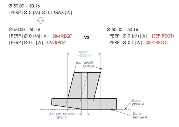
I wasn't thinking about it this way. The picture below should help to clarify my point. My apologies that it shows external FOS rather than internal FOS as in Fig. 6-15.

snapshot_vrckeu.jpg


For the part as shown:
- When both callouts are separate requirements, the measured perpendicularity value for the RFS callout could first be reported as 0.1, and then the part would be tilted to make the size of the RAME conforming (equal to or less than 50.16);
- When both callouts are simultaneous requirements, they have to be considered in a single datum-to-datum feature relationship, therefore for a conforming size of the RAME, the measured perpendicularity value for the RFS callout will always be less than 0.1.

tim_member,

See my response (15 Aug 19 16:12). Could you explain why you believe the single FCF in 6-15 is an example of simultaneous requirements, considering that concept does not apply to perpendicularity (and it is shown as a single callout, not two separate)? And additionally why you think it might be a valid callout despite the fact that it is a single MMC control for which the surface interpretation must take precedence?
 
Does the formula for actual value for MMC surface interpretation, if applied on a hole, means that the actual value for an acceptable hole must always be negative?

If there is a nonzero tolerance at MMC the RAME may be less than (positive actual value), equal to (zero actual value), or greater than the MMC size (negative actual value). If there is zero tolerance at MMC, the RAME may still be less than or equal to the MMC size.

And for the axis interpretation, isn't the actual value just the diameter of the smallest cylinder which is basically constrained to the DRF and contains the axis of the UAME?

Per my response (17 Aug 19 03:18) I think it may involve such a diameter, but the actual value for MMC is not equal to it. Lets call this diameter D.

Taking table 5-3 and b = D/2 it defines a tolerance zone for MMC axis interpretation as follows:

D/2 = actual_value/2 + (size_UAME/2 - size_MMC/2)

Rearranging we get:

actual_value = D + size_MMC - size_UAME

Conversely for RFS the tolerance zone is defined as:

D/2 = actual_value/2

Therefore actual_value = D for RFS.
 
chez311 said:
Could you explain why you believe the single FCF in 6-15 is an example of simultaneous requirements, considering that concept does not apply to perpendicularity (and it is shown as a single callout, not two separate)?

Because it is a single callout applied to a single feature.

chez311 said:
And additionally why you think it might be a valid callout despite the fact that it is a single MMC control for which the surface interpretation must take precedence?

Because 2009 standard doesn't say that for MMC and LMC callouts the surface interpretation is the default. It says that when the axis and surface interpretations give conflicting results (i.e., when one gives FAIL, while the other gives PASS, or vice versa), the surface interpretation shall take precedence. I know you have been saying something different, but that just means I disagree with you ;-)
 
Because it is a single callout applied to a single feature.

Thats an interesting definition of simultaneous requirements.

tim_member said:
Because 2009 standard doesn't say that for MMC and LMC callouts the surface interpretation is the default. It says that when the axis and surface interpretations give conflicting results (i.e., when one gives FAIL, while the other gives PASS, or vice versa), the surface interpretation shall take precedence

Actually as I've pointed out several times the exact wording of the standard utilizes the term "equivalence". Nowhere in the standard is mentioned pass or fail, or that this equivalence means as such. I'd be interested if another perhaps more knowledgeable member than I weighed in on this, however I've already linked to another thread where a well respected member provided a very clear opinion on this very topic in my post on (16 Aug 19 20:22).

Ignoring that for a moment, for a pass or fail evaluation to be provided the feature must be measured and an actual value calculated for both interpretations to determine if indeed it does pass or fail. Do you see a way to evaluate fig 6-15 with a surface interpretation?
 
chez311 said:
Thats an interesting definition of simultaneous requirements.

This wasn't to provide a definition of simultaneous requirements, so let me try from another angle by using the following - maybe not too realistic - example:
An inspector is told to evaluate the conformance of the feature from my illustration to the MMC MAX callout with the use of axis interpretation. For the shown orientation of the part relative to the datum plane A, the measured axis perpendicularity value is 0.1. Technically, this is all that is required from inspection point of view because feature axis is conforming to the specification. But the inspector is educated enough to know that in case of extreme orientation error values, as shown in Fig. 5-2 in Y14.5.1M-1994, the virtual condition boundary (dia. 50.16) might be violated by the surface of the feature, therefore he decides to perform additional RAME size check. Since the check is giving a value greater than dia. 50.16, he is taking the advantage of the candidate datum concept by trying to tilt the part to see if the size of the RAME could be adjusted to dia. 50.16 or perhaps smaller. Once he has done it (assuming he was able to), he is now going to re-measure and report the axis perpendicularity value.

What I am trying to say here is that he will not report the initial value of 0.1, but the re-measured smaller value, and that the measurements he performed are equivalent to the check against the duo with SIM REQTs.


chez311 said:
Actually as I've pointed out several times the exact wording of the standard utilizes the term "equivalence". Nowhere in the standard is mentioned pass or fail, or that this equivalence means as such.

Actually, I would say the term "equivalence" is only used in the pass/fail context. And you already provided the numbers of the applicable paragraphs in Y14.5-2009 - 6.4.5 and 7.3.3.1. These paragraphs clearly refer to Fig. 7-6, which shows the difference between the two interpretations in pass/fail terms. The explanatory note in this figure says: "If size requirements are met, and the virtual condition is not violated [PASS per the surface interpretation], the feature is acceptable even if the axis of the unrelated actual mating envelope feature is outside the positional tolerance zone [FAIL per the axis interpretation]".

Y14.5.1M-1994 doesn't add anything to the discussion, in my opinion, because the paragraph that talks about the equivalency of the interpretations uses Figs. 5-1 and 5-2 and these figures show nothing but scenarios where a feature of size controlled with a position tolerance at MMC could be tagged PASS using one interpretation but FAIL using the other interpretation.


chez311 said:
Ignoring that for a moment, for a pass or fail evaluation to be provided the feature must be measured and an actual value calculated for both interpretations to determine if indeed it does pass or fail. Do you see a way to evaluate fig 6-15 with a surface interpretation?

Yes, I would see a way, but first the definition of the surface interpretation for MMC and LMC tolerances, as given in Y14.5-2009 (para. 7.3.3.1(a)) and Y14.5.1M-1994 (Table 5-2 -> MMC and LMC columns), would have to change to allow for checking a feature surface against size-variable boundary instead of a constant Virtual Condition boundary in certain cases. I guess it is in line with your point of view.
 
pylfrm said:
tim_member,

Can you describe a part that would be rejected by the ASME Y14.5-2009 Fig. 6-15 scheme, but accepted by the scheme I described?

I wasn't thinking about it this way. The picture below should help to clarify my point. My apologies that it shows external FOS rather than internal FOS as in Fig. 6-15.

I still haven't succeeded in imagining a part that is rejected by one scheme and accepted by the other. It seems plausible that such a part exists, but if not, then the two schemes must be equivalent. I'll try to give it some more thought.


Does the formula for actual value for MMC surface interpretation, if applied on a hole, means that the actual value for an acceptable hole must always be negative?

No. The actual value for an acceptable feature must be less than or equal to the tolerance value in the feature control frame. This is pretty much how "actual value" is defined in ASME Y14.5.1M-1994, regardless of feature type or tolerance interpretation.


And for the axis interpretation, isn't the actual value just the diameter of the smallest cylinder which is basically constrained to the DRF and contains the axis of the UAME?

Not for MMC or LMC tolerances. See above and below.


If there is a nonzero tolerance at MMC the RAME may be less than (positive actual value), equal to (zero actual value), or greater than the MMC size (negative actual value). If there is zero tolerance at MMC, the RAME may still be less than or equal to the MMC size.

For a hole that satisfies the tolerance, the last sentence should say "greater than" instead of "less than".


Per my response (17 Aug 19 03:18) I think it may involve such a diameter, but the actual value for MMC is not equal to it. Lets call this diameter D.

Taking table 5-3 and b = D/2 it defines a tolerance zone for MMC axis interpretation as follows:

D/2 = actual_value/2 + (size_UAME/2 - size_MMC/2)

Rearranging we get:

actual_value = D + size_MMC - size_UAME

Conversely for RFS the tolerance zone is defined as:

D/2 = actual_value/2

Therefore actual_value = D for RFS.

Correct.


pylfrm
 
chez311 said:
If there is a nonzero tolerance at MMC the RAME may be less than (positive actual value), equal to (zero actual value), or greater than the MMC size (negative actual value). If there is zero tolerance at MMC, the RAME may still be less than or equal to the MMC size.

Sure! I get it now. Thanks.[thumbsup]

pylfrm said:
For a hole that satisfies the tolerance, the last sentence should say "greater than" instead of "less than".

That makes it even more clear. Thank you both!
 
Status
Not open for further replies.

Part and Inventory Search

Sponsor