Continue to Site

Eng-Tips is the largest engineering community on the Internet

Intelligent Work Forums for Engineering Professionals

  • Congratulations waross on being selected by the Eng-Tips community for having the most helpful posts in the forums last week. Way to Go!

Fig. 6-15, para. 6.4.4 Y14.5-2009 1

Status
Not open for further replies.

Burunduk

Mechanical
May 2, 2019
2,361
6.4.4:
"There may be applications where the full additional tolerance allowable may not meet the functional requirements.
In such cases, the amount of additional tolerance may be limited by stating a MAX following the MMC modifier. See Fig. 6-15."

1. dia. 0.1MAX shown in fig. 6-15 - is it the maximum additional ("bonus") tolerance (as I interpret the text quoted), or is it the maximum total (bonus + specified) tolerance of perpendicularity (as I think would be clearer and make more sense?). I am aware that in this example they are the same, but what if the tolerance at MMC was more than zero?

2. Is the concept applicable for position, or just orientation? Is there a good reason it is only in chapter 6, but not 7?
 
Replies continue below

Recommended for you

Yes, I was referring to the fact that the diameter of the tolerance zone to which the feature axis must conform could be negative. This simply shouldn't let anyone think that the actual value for axis interpretation is not determinable.
 
If had to come up with my own way to calculate the actual value for a hole by the surface interpretation, the calculation I would suggest: actual_value = size_UAME - size_RAME

You have just described the inverse of the actual value for RFS surface interpretation per Y14.5-1994 (actual_value = size_RAME - size_UAME), which per Y14.5-2018 is explicitly not valid as I noted on (21 Aug 19 13:59).

ASME Y14.5.1M-1994 surface interpretation actual values for RFS position are as follows:
internal feature: actual_value = size_UAME - size_RAME
external feature: actual_value = size_RAME - size_UAME​


The reasoning is simple: If there is no location, orientation or form deviation, size_UAME = size_RAME, so the feature utilizes zero tolerance, in other words, the deviation from true position/perfect orientation is zero.

In the context RFS tolerances, it makes sense to say that a feature has perfect location when its UAME axis is coincident with true position. A tolerance zone size of zero is sufficient to contain it, and it's not possible to get any better than that. Perhaps more importantly, it's not possible to satisfy the tolerance by a larger margin.

I don't think it makes sense to consider MMC tolerances in terms of deviation from perfection. The location of the UAME axis is irrelevant because it doesn't tell you anything about whether the feature surface violates the virtual condition boundary. It's always possible to satisfy the tolerance by a larger margin (until the feature disappears) so it seems hard to justify calling any particular condition "best" or "perfect".


Example:
Specified hole diameter 10+-0.2
Perpendicularity requirement with reference to datum feature A: 0.1 at MMC.
Produced UAME size: 10.1
Produced RAME: 9.85.

First, what should the actual value be compared to? Everyone learns early at any GD&T training that departure of feature size from MMC gives additional tolerance that can be added to the specified tolerance value, to calculate the total allowed tolerance.
For this case departure from MMC is 10.1-9.8=0.3, so there is up to 0.1+0.3=0.4 orientation tolerance that can be utilized.
How much of it is used by the surface deviation of the feature from a boundary which is equal to its size and oriented perfectly? That is the "actual value" as I would prefer it to be defined: 10.1 (UAME dia.) - 9.85 (RAME dia.) = 0.25.
That is less than the allowed 0.4 for this UAME size, so the hole conforms to the specifications.

You might also say that the hole conforms to the perpendicularity requirement by a margin of 0.15, calculated as 0.1 + (10.1 - 9.8) - (10.1 - 9.85). That same result can be calculated as 0.1 - (9.8 - 9.85) though, and the latter method avoids involving the UAME size. I think this elimination of an extraneous factor is advantageous just for the sake of simplicity, but it also allows the method to be applied when less information is available.


pylfrm
 
chez311 said:
I see no reason why the UAME would be involved in MMC surface interpretation calculation of actual value as it conflates axis deviation with surface deviation.

I really don't see how it does that. The actual value determination for surface interpretation as I proposed, doesn't involve deriving the axis of the UAME, and the actual value determination based on axis interpretation per Y14.5.1 para. 5.2.2 (c) doesn't involve measurement of the UAME size as my suggestion does. Could you clarify where in my suggestion you see the problematic mixture of axis and surface concepts?

pylfrm said:
ASME Y14.5.1M-1994 surface interpretation actual values for RFS position are as follows:
internal feature: actual_value = size_UAME - size_RAME

If my suggestion turns out to be the same formula as the RFS surface interpretation, all the better.
I don't see any issue with calculating them the same way mathematically, with the only difference being that for the MMC case there is an additional tolerance that adds to the specified tolerance in the feature control frame as follows from the departure of the feature size from MMC.

Come to think of it, it can be said that my proposed scheme probably does eliminate the size dependency of the actual value. When substracting the RAME diameter from the UAME diameter, size as a property is being reduced. In other words, the difference between the two sizes of coaxial boundaries: (1) a boundary of perfect location/orientation and (just) the size of the UAME, and (2) the RAME boundary, will only depend on surface orientation/location deviations, regardless the value of size itself. That is a good thing.

pylfrm said:
That same result can be calculated as 0.1 - (9.8 - 9.85) though, and the latter method avoids involving the UAME size.

I'm not sure I understand why there is a tendency to eliminate the UAME size from surface-related calculations. I can tell that for the example we are discussing, I like the 0.15 result less than 0.25, as it wouldn't lead to the equivalency of the calculated actual value with the axis interpretation. Conversely, the 0.25 result of my proposed calculation is either nearly the same or the same as the axis interpretation would produce, and achieved only by surface evaluations, as I mentioned, without deriving the axis of the UAME.

The current definitions in Y14.5.1M-1994 lead to completely different actual values for the two interpretations, surface and axis.
I don't see a good reason for having two essentially different interpretations leading to completely different results- for the same specification, and then having to make efforts to decide at which cases one interpretation takes precedence over the other. That is one messy double definition of a geometrical tolerance.

pylfrm said:
I don't think it makes sense to consider MMC tolerances in terms of deviation from perfection.

Axis interpretation of MMC tolerances is already defined with these terms, like it or not. Why shouldn't both interpretations be in line with each other?
For the surface, consider it deviation from surface perfection, not deviation from axis perfection. Every other concept in ASME Y14.5 is explained in these terms, so why not MMC tolerances?

Edited for a more detailed explanation.


ASME Y14.5.1M-1994 surface interpretation actual values for RFS position are as follows:
internal feature: actual_value = size_UAME - size_RAME
external feature: actual_value = size_RAME - size_UAME

Yes thank you for the correction I had it backwards.

the actual value determination based on axis interpretation per Y14.5.1 para. 5.2.2 (c) doesn't involve measurement of the UAME size as my suggestion does
No, but it involves consideration of the UAME axis (b = radius of the smallest cylinder constrained to the DRF which contains the UAME axis) and the tolerance zone to which it must conform directly involves the size of the UAME (b = actual_value/2 + (size_UAME/2 - size_MMC/2). If the convention were the same as the surface interpretation then the actual value would too.

Could you clarify where in my suggestion you see the problematic mixture of axis and surface concepts?

The UAME is the envelope which defines the feature's axis. Whether you are talking about the size of this envelope or the axis itself, you are introducing a value which involves the features axis.

The current definitions in Y14.5.1M-1994 lead to completely different actual values for the two interpretations, surface and axis. I don't see a good reason for having two essentially different interpretations leading to completely different results- for the same specification, and then having to make efforts to decide at which cases one interpretation takes precedence over the other

The choice by the committee to designate the minimum value of b as the actual value for the axis interpretation is the convention we are working with due to the wording of the standard. As I already mentioned several times, if this was instead the minimum t0 then the actual value for both the axis and surface interpretations would be directly comparable - this would be my choice of actual value for the MMC axis interpretation if I had my way. Such a comparison can still be made, if we evaluate minimum t0 of each interpretation.

Furthermore, the "effort to decide" which interpretation takes precedence is due to the unfortunate wording in the 2009 standard which portrays the two interpretations as "equivalent" except for cases of "extreme" form/orientation deviation. As I showed at length in my post (21 Aug 19 13:59) this has been eliminated in 2018 - the surface interpretation takes precedence for MMC/LMC across the board with a few exceptions which have nothing to do with evaluation of "equivalence".

The surface interpretation must be the final word on whether the virtual condition has been violated. As it stands now, the axis interpretation may accept a feature which violates the virtual condition while the surface interpretation will reject it. There is no situation where the surface interpretation will accept such a feature. Your proposal would make it so it is possible for the surface interpretation to accept a feature which violates the virtual condition. A feature similar to Y14.5.1-1994 fig 5-1 (but perhaps less exaggerated) or 5-2 has the potential to not be rejected by your scheme. A direct evaluation of the RAME to your MMC size would reject either of these - the current MMC surface interpretation already accomplishes this.
 
chez311 said:
The UAME is the envelope which defines the feature's axis. Whether you are talking about the size of this envelope or the axis itself, you are introducing a value which involves the features axis.

Sorry, don't follow this logic. If the axis is not derived during an evaluation, how is it being involved? Currently by the Y14.5.1M-1994, is the RFS surface interpretation any less "surface" than the MMC surface interpretation? just because the UAME diameter is involved?

chez311 said:
Your proposal would make it so it is possible for the surface interpretation to accept a feature which violates the virtual condition. A feature similar to Y14.5.1-1994 fig 5-1 (but perhaps less exaggerated) or 5-2 has the potential to not be rejected by your scheme. A direct evaluation of the RAME to your MMC size would reject either of these - the current MMC surface interpretation already accomplishes this.

Fig. 5-1 shows a feature that would be accepted by the surface interpretation, (with an acceptable actual value as defined in the standard), but rejected by the axis interpretation. So I suppose this one is irrelevant.

As for the shaft example from fig. 5-2, I suppose you suggest that my proposal for surface interpretation would accept that feature similar to how the axis interpretation accepts it.

We shall check it with an example.
Suppose that the drawing says:
*Shaft diameter = 10+-0.2
*Position within 0.1 at MMC referencing datum feature A.
The shaft was produced at:
size_UAME = 9.9 (measured without deriving the feature axis!!!)
size_RAME = 10.31
The total allowed tolerance is: tolerance value + departure from MMC = 0.1+(10.2-9.9)=0.4
Calculation of an actual value for an external feature per my proposal is same as for RFS:
actual_value = size_RAME - size_UAME
actual_value = 10.31-9.9=0.41
The actual value exceeds the total allowed tolerance by 0.01, therefore the feature is rejected.
The virtual condition boundary is size_MMC+ "tolerance value"=10.2+0.1=10.3
It is clear that the 10.31 RAME violated the virtual condition by 0.01, exactly as the calculated actual value indicates.


chez311, pylfrm, any additional insight on this subject considering the above numerical example?

Right now the benefit I see in calculating the actual value for MMC surface interpretation the way I suggested is matching with the "additional tolerance" for departure from MMC as described in Y14.5. In addition, it is possible to get comparable results with the axis interpretation while keeping the advantage of not accepting nonconforming features as in fig. 5-2 of Y14.5.1M-1994. I think that as long as the RAME participates directly in the evaluation, unlike in the axis interpretation scenario, acceptance of a feature such as in fig. 5-2 is impossible.
Am I wrong?
 
If the axis is not derived during an evaluation, how is it being involved? Currently by the Y14.5.1M-1994, is the RFS surface interpretation any less "surface" than the MMC surface interpretation?

I would consider them (UAME axis/boundary) two sides of the same coin.

Quantifying one or the other (RFS vs MMC surface interpretation) as "more or less surface" is not really my point - they both certainly involve the surface, its just how this is accomplished for each. The fact that your proposed method was chosen by the committee to represent the RFS surface interpretation and not MMC should tell you something - this was not an arbitrary choice. Comparing the UAME to RAME attempts to isolate orientation/position orientation from the effects of size, which I believe to be counterproductive for MMC.

In addition, it is possible to get comparable results with the axis interpretation

MMC is at its core a surface control, which is reinforced by the decision in 2018 to eliminate (most) of the wording suggesting any "equivalence" between the axis and surface interpretations. Trying to get the results from the surface interpretation actual value to match that of the axis interpretation I think is a mistake - if anything it should be the other way around, as utilization of the feature axis to determine MMC conformance is an approximation.

Ultimately I see no reason the UAME should be involved, even though I do not think there is a situation where your scheme will accept a feature which violates the virtual condition. This is because the inclusion of the UAME is extraneous - your suggestion can be reduced down to the current definition of the surface interpretation.

Lets take your current definition of the tolerance zone (note this is the same as the MMC axis interpretation) which you have called the "total allowed tolerance"
total_allowed_tolerance = t0 + (size_UAME - size_MMC)

and your definition of the actual value (note this is the same as the RFS surface interpretation)
actual_value = size_UAME - size_RAME

If I follow your logic, essentially the feature is accepted if:
actual_value ≤ total_allowed_tolerance

Lets substitute in the previous equations
size_UAME - size_RAME ≤ t0 + size_UAME - size_MMC

size_UAME cancels out on either side, and rearranging we get
size_RAME ≥ size_MMC - t0

This is the definition of the surface interpretation for MMC per Y14.5.1 table 5-2 and can be solved for the actual value as we've already shown. The extra step of essentially adding size_UAME to both sides of the equation gets the same result and is not necessary.
 
I would consider them (UAME axis/boundary) two sides of the same coin.

I think it's important to recognize that UAME size can be measured without gaining any information about axis orientation or location. Similarly, axis orientation or location can be measured without gaining any information about UAME size, although this may be less common.

I am in full agreement with the rest of the post.


pylfrm
 
chez311 said:
Comparing the UAME to RAME attempts to isolate orientation/position orientation from the effects of size, which I believe to be counterproductive for MMC.

I think it is enough that the effect of size is taken into account during the allowed tolerance calculation when determining how much additional tolerance is available if any. Accounting for size during actual value calculation is an attempt to make the position control into some combined size + position control. This attempt will not always be successful; For nonzero tolerance at MMC, calculating the actual value for hole position by size_MMC - size_RAME may or may not reject a feature that is located and oriented well enough (or even perfectly) but doesn't conform to size limits, so the size control aspect of the process is not reliable anyway.
Apart from that, not having the additional tolerance for departure from MMC represented by the amount of tolerance that the actual value is compared to is confusing and does a poor job at reflecting the reasoning behind MMC tolerances. GD&T instructors work hard to convince people who read drawings that MMC is good for manufacturing and allows for additional tolerance. Having the maximum allowable actual value the same as the specified tolerance value in the feature control frame doesn't serve that purpose. If the axis interpretation actual value was calculated in a similar manner as you and pylfrm proposed, it would lead to conflict with the very basic principle of MMC tolerance calculation as introduced in figure 2-12 in ASME Y14.5-2009, specifically the "TOL diameter" column of the table.
 
Accounting for size during actual value calculation is an attempt to make the position control into some combined size + position control.

To be precise - I would only say the current definition "accounts" for size insofar as it does not attempt to remove its effects. As I've already asserted several times, the concept of MMC position connects the concepts of size and position - I neither understand nor share your opinion that we should attempt to separate the two.

The word attempt is appropriate too because evaluation of the UAME is only a good estimation of size as long as there is little to no form error - the greater the form error the less the UAME size relates to actual size deviation per the swept spheres definition of size.

For nonzero tolerance at MMC, calculating the actual value for hole position by size_MMC - size_RAME may or may not reject a feature that is located and oriented well enough (or even perfectly) but doesn't conform to size limits, so the size control aspect of the process is not reliable anyway

Again, I would say the current definition does not truly "account for" or "control" size (see my above) - it simply establishes a fixed boundary which the feature may not violate. I don't think I ever said MMC position should reject a feature which is out of tolerance for size only but does not violate virtual condition. Size is still a separate check.

Apart from that, not having the additional tolerance for departure from MMC represented by the amount of tolerance that the actual value is compared to is confusing and does a poor job at reflecting the reasoning behind MMC tolerances. GD&T instructors work hard to convince people who read drawings that MMC is good for manufacturing and allows for additional tolerance. Having the maximum allowable actual value the same as the specified tolerance value in the feature control frame doesn't serve that purpose.

This may be a chicken or the egg scenario, however I would not say that "additional tolerance for manufacturing" is necessarily the driving force behind MMC. I would say this is perhaps a situation where the design intent (fixed boundary not to be violated) results in a desirable characteristic for manufacturing (additional variation possible due to deviation in size). The additional variation possible is just a result of the geometry involved with a fixed boundary and a feature of variable size that can be pointed out as a net benefit for manufacturing. The concept of an expanding tolerance zone based on size is needed for analysis of a theoretical feature such as an axis - for the surface interpretation no such analogy is necessary, the surface can vary in any way possible as long as it does not violate the fixed boundary (virtual condition) and conforms to the limits of size. The concept of "additional tolerance" as suggested by an expanding tolerance zone doesn't really apply to the surface interpretation - just take a look at the use of the term "additional variation" in Y14.5-2018 5.9.4.1 Explanation of the Surface Method and "available tolerance" in Y14.5-2018 5.9.4.2 Explanation of the Axis Method. Its a subtle but important distinction.

If the axis interpretation actual value was calculated in a similar manner as you and pylfrm proposed, it would lead to conflict with the very basic principle of MMC tolerance calculation as introduced in figure 2-12 in ASME Y14.5-2009, specifically the "TOL diameter" column of the table.

The actual value for the axis interpretation is simply a convention chosen by the committee, and it is one I have already resigned myself to. Though if changed, it would not conflict with anything. Whether or not the actual value is the minimum t0 or minimum b (what I was referring to as D/2) the definition of the tolerance zone within which the feature axis must fall would remain the same. In fact, nothing on the figure to which you have referred translates to an actual value calculation - its main focus is the calculation of virtual condition and resultant condition (this would be unchanged) and the "TOL" column is equivalent to our calculations of the size of the tolerance zone per 5-3 previously (2b = t0 + size_UAME - size_MMC) within which the axis must fall (again - this would also be unchanged) - ie: where possible variations of size_UAME is the series [30.5 30.4 30.3 30.2 30.1] the calculation of the tolerance zone diameter would still be [0.5 0.4 0.3 0.2 0.1].

This is all to say, the calculations shown in 2-12 and similar figures is for visualization only and as I showed on my post (21 Aug 19 13:59) the new 2018 standard says as much. It is taught because it is easy to visualize but it is NOT the final word. Such calculations start to break down with increasing form error.
 
I think it is enough that the effect of size is taken into account during the allowed tolerance calculation when determining how much additional tolerance is available if any.

Feature size is irrelevant as far as an MMC position tolerance is concerned. All that matters is whichever single point on the feature surface is closest (in the case of an internal feature) to true position. The rest of the feature has no bearing whatsoever on conformance to the tolerance. By involving size in the calculations you are forcing collection and consideration of irrelevant data.


Accounting for size during actual value calculation is an attempt to make the position control into some combined size + position control.

I claim that it's better for actual feature size to remain uninvolved in the actual value calculation. If anything, "accounting for size" sounds more applicable to your suggested method of actual value calculation.

An MMC position tolerance does place an inherent limit on the size of the feature, but that's an unavoidable consequence of the meaning of the tolerance. It has nothing to do with actual value calculation.


For nonzero tolerance at MMC, calculating the actual value for hole position by size_MMC - size_RAME may or may not reject a feature that is located and oriented well enough (or even perfectly) but doesn't conform to size limits, so the size control aspect of the process is not reliable anyway.

It doesn't make sense to say that a feature is "located and oriented well enough" if it doesn't conform to the tolerance. Conformance to the tolerance is basically the definition of "good enough" in this case.

I'm not sure what you might mean by "located and oriented perfectly" in the context of an MMC position tolerance. I wouldn't call something perfect unless it conforms to the tolerance by the largest possible margin. There's no well-defined upper limit on the margin by which a hole conforms to an MMC position tolerance, so perfection does not seem like a meaningful concept here.

For a related example, consider a size specification of diameter 9.8 MIN for an internal feature. Can perfection with regard to that specification be defined? I would think not.


Apart from that, not having the additional tolerance for departure from MMC represented by the amount of tolerance that the actual value is compared to is confusing and does a poor job at reflecting the reasoning behind MMC tolerances.

The whole notion of "additional tolerance for departure from MMC" is only used for the axis interpretation. A lot of potential confusion can be avoided by recognizing that this is only an approximation to the definition which takes precedence.

The purpose of an MMC tolerance is to create a boundary of fixed size that is guaranteed to not be violated by the material of the feature. I'd say comparing the actual value to a fixed tolerance value reflects this just fine. It tells you the margin by which that boundary is or is not violated.


GD&T instructors work hard to convince people who read drawings that MMC is good for manufacturing and allows for additional tolerance. Having the maximum allowable actual value the same as the specified tolerance value in the feature control frame doesn't serve that purpose.

I think there are much better ways to explain that benefit than "allows for additional tolerance". The tolerance on the drawing (i.e., the requirement which must be satisfied) has a fixed meaning; it does not change based on the characteristics of the part being assessed.

Instead, why not explain that producing a hole with a larger size makes it easier to avoid violating the position tolerance boundary? This certainly seems like the simplest approach to me. If for some reason you insist on the axis interpretation, why not explain that producing a hole with a larger UAME size results in a larger diameter of the tolerance zone for the UAME axis? There's no particular need to even consider actual values if you just want to discuss the meaning of tolerances.


If the axis interpretation actual value was calculated in a similar manner as you and pylfrm proposed, it would lead to conflict with the very basic principle of MMC tolerance calculation as introduced in figure 2-12 in ASME Y14.5-2009, specifically the "TOL diameter" column of the table.

ASME Y14.5-2009 does not address the subject of actual values or even use the term.

pylfrm
 
I think it's important to recognize that UAME size can be measured without gaining any information about axis orientation or location. Similarly, axis orientation or location can be measured without gaining any information about UAME size, although this may be less common.

I guess thats some unfortunate wording on my part. I just meant that by establishing the UAME boundary the UAME axis is also established whether or not its position/orientation is measured (though I guess one could argue semantics or philosophically whether its actually established if we never measure it), and in order to establish the UAME axis the UAME boundary must first be established whether or not its size is measured. Perhaps this is an obvious conclusion, and your point is well taken.

I'm glad you agree with the rest of that post - its good to know I'm on the right track as I hold your opinion in very high regard, it took me a little bit to realize the proposed scheme is in fact not fundamentally different but basically just a restatement of the current MMC surface interpretation with extra steps.

The whole notion of "additional tolerance for departure from MMC" is only used for the axis interpretation. A lot of potential confusion can be avoided by recognizing that this is only an approximation to the definition which takes precedence.

Seems like we're still mostly on the same wavelength I think (also within 5 minutes...!) and this is the concept that seems to be a major sticking point which I also tried to address in my post from a similar angle. Trying to make the surface interpretation provide a result which approximates the "additional tolerance" concept found in the axis interpretation does not seem to me a worthwhile exercise.

I claim that it's better for actual feature size to remain uninvolved in the actual value calculation. If anything, "accounting for size" sounds more applicable to your suggested method of actual value calculation.

An MMC position tolerance does place an inherent limit on the size of the feature, but that's an unavoidable consequence of the meaning of the tolerance. It has nothing to do with actual value calculation.

Excellent point - I skirted around this when I said 'the current definition "accounts" for size insofar as it does not attempt to remove its effects' but this may be somewhat shaky and inviting misinterpretation, although maybe you get what I mean? I think it may be more proper to say size is not involved in the actual value calculation for the surface interpretation since in reality size (per the swept spheres or the approximation afforded by the UAME) does not appear in the equation.
 
pylfrm said:
I claim that it's better for actual feature size to remain uninvolved in the actual value calculation. If anything, "accounting for size" sounds more applicable to your suggested method of actual value calculation.

I claim the very same thing (as the bolded part), but I say that it is the existing method that accounts for size - unnecessarily.
Let us consider an example of a hole defined with the requirements of:
Size: dia. 10+-0.2
Position: 0.1 at MMC with reference to the relevant datum features.
If the produced feature fulfills the condition that the envelope of RAME is coincident with the envelope of UAME, for example size_UAME = size_RAME = 10, this is a feature that I consider to be produced "perfectly" in terms of the surface interpretation MMC position (and note that I didn't mention the feature axis). I say so because the meaning of this condition is that the envelope that is expanded within that feature until being constrained by the hole surface itself (contacting on the highest points) will be oriented and located perfectly to the datum features. Again, the axis is not involved, as the evaluation is performed just by comparing the sizes of UAME and RAME. The actual value per the size_MMC - suze_RAME calculation is 9.8-10=-0.2.
Now imagine that that same "perfect" feature is being proportionally scaled down to the UAME size of 9.71, which also becomes its RAME envelope size. According the calculation of actual_value = size_MMC - size_RAME we get: actual_value = 9.8 - 9.71 = 0.09, pretty close to t0 of 0.1 and pretty close to be rejected, because of the effect of its size during the evaluation of position conformance (position with any kind of modifier in the feature control frame is still a control position: I.e. location and orientation).
Going by my proposed calculation of actual_value = size_UAME - size_RAME would produce the result of 9.71 - 9.71 = 0, I.e., the feature as produced utilizes 0 tolerance of position, therefore it is positioned as accurately as it can be. Obviously, it will be rejected based on the limits of size inspection, so no worries should arise regarding the passing of nonfunctional parts. If so it really isn't my suggested method that accounts for size, but the method that the mathematical definition provides.

chez311, pylfrm, I do realize that the main goal of MMC tolerances is to make sure a fixed boundary is not being violated by the feature. But if we have two different interpretations to the same geometrical tolerance and one is an approximation of the other as you say, wouldn't it make sense for the actual value calculations for both interpretations to produce results that are similar or close enough to each other?
One thing that I didn't notice before though - my proposed calculation is only good for produced features that fulfill the condition that the RAME is less than the VC for shafts, or greater than the VC for holes. In cases where the RAME violates the VC, the feature should be rejected and it is possible to report the difference between the VC and the RAME as the amount by which the virtual condition boundary is violated.
 
According the calculation of actual_value = size_MMC - size_RAME we get: actual_value = 9.8 - 9.71 = 0.09, pretty close to t0 of 0.1 and pretty close to be rejected, because of the effect of its size during the evaluation of position conformance (position with any kind of modifier in the feature control frame is still a control position: I.e. location and orientation)

The value of 0.09 just says that some portion of the feature is 0.1-0.09=0.01 away from violating virtual condition. It does not matter if that means all points on the feature are this far away from the virtual condition as in your example or if only a small portion is this far away (a larger hole, offset slightly resulting in the same RAME) - the result will be the same. Your suggestion would produce different actual values in both these cases even though neither would be any closer/further from violating virtual condition.

I do realize that the main goal of MMC tolerances is to make sure a fixed boundary is not being violated by the feature.

Its not just the main goal, its the very definition. From Y14.5-2018 "5.9.4.1 Explanation of the Surface Method. When a geometric tolerance is applied on an MMC basis, the feature’s surface shall not violate the VC boundary."

But if we have two different interpretations to the same geometrical tolerance and one is an approximation of the other as you say, wouldn't it make sense for the actual value calculations for both interpretations to produce results that are similar or close enough to each other?

Yes it would make sense. This is why if I've said several times that in my mind the minimum t0 should be the actual value for both interpretations as it would accomplish what you say, however I have to work with what the wording of the standard says. While I don't know why they changed the definition of actual value for the axis interpretation, its not terribly critical as we know that it is but an approximation of conformance as the surface interpretation takes precedence.

What doesn't make sense to me is trying to get the surface interpretation to replicate the current definition of actual value for the axis interpretation (minimum value of b = D) by involving the UAME size. While inherently not making sense to me (trying to get the surface interpretation to match the axis interpretation results) it falls apart when increasing form error is introduced.

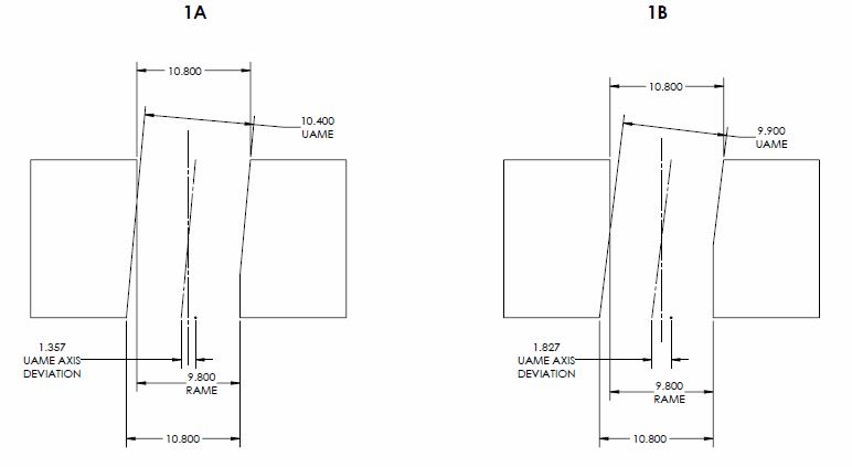
If we take a look at the cases below, when form error is introduced comparison of the UAME and RAME provides no relevant information as well as doesn't match the axis interpretation actual value (as we know). In reality this definition of actual value (size_UAME - size_RAME) has little use when considered by itself, and is only really useful in comparison with your "total allowed tolerance" (t0 + size_UAME - size_MMC). I already showed that when compared, the size_UAME term cancels out and is not necessary.

In both the below, lets take the theoretical specification of:
dia. 10 +0.8/-0.2
|POS|dia. 0(M)|A|B|C|

1)
Y14.5.1 surface interpretation (both) actual_value = size_MMC - size_RAME = 9.8 - 9.8 = 0
Your surface interpretation proposal (1A) actual_value = size_UAME - size_RAME = 10.4 - 9.8 = 0.6
Your surface interpretation proposal (1A) total_allowed_tolerance = t0 + (size_UAME - size_MMC) = 0 + 10.4 - 9.8 = 0.6
Your surface interpretation proposal (1B) actual_value = size_UAME - size_RAME = 9.9 - 9.8 = 0.1
Your surface interpretation proposal (1B) total_allowed_tolerance = t0 + (size_UAME - size_MMC) = 0 + 9.9 - 9.8 = 0.1
Y14.5.1 axis interpretation (1A) actual_value = D/2 = 1.357/2 = 0.6785
Y14.5.1 axis interpretation (1A) tolerance_zone = 0.6*
Y14.5.1 axis interpretation (1B) actual_value = D/2 = 1.827/2 = 0.9135
Y14.5.1 axis interpretation (1B) tolerance_zone = 0.1*

As you can see from the features shown by 1A and 1B, neither is any closer/further from violating virtual condition however both your proposal and the axis interpretation produce wildly different results. This is why the comparison of the UAME and RAME is only useful in cases of perfect form. What do the values of 0.6 and 0.1 tell us? It does not agree with the axis interpretation due to the form error. In fact, the latter which should be "more perfect" in your definition (size_UAME nearing size_RAME) actually results in a UAME which is even further from being coincident to the RAME (shown by the axis interpretation actual_values of 0.6785 and 0.9135).

Your proposal for actual value is only useful when compared to the "total allowed tolerance" (0.6-0.6=0 or 0.1-0.1=0) because, as I showed earlier, the size_UAME term cancels out and you are left with the current definition of MMC surface interpretation.

*same as your "total_allowed_tolerance"

snippet_A_utjftf.jpg


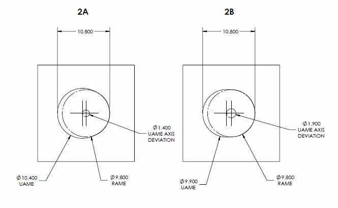
2) Same calculations as case (1) except for the below
Y14.5.1 axis interpretation (2A) actual_value = D/2 = 1.4/2 = 0.7
Y14.5.1 axis interpretation (2B) actual_value = D/2 = 1.9/2 = 0.95

A similar case as (1) however with a UAME axis parallel to the RAME. As you can see, the UAME can be located as far from the RAME as the limits of size will allow and the relative size of the UAME and RAME tells us just as little as it does in case (1).

snippet_2A_zcs4i8.jpg


If the produced feature fulfills the condition that the envelope of RAME is coincident with the envelope of UAME, this is a feature that I consider to be produced "perfectly" in terms of the surface interpretation MMC position (and note that I didn't mention the feature axis)

As I've shown above, comparison of the size of the UAME and RAME does not guarantee that they are coincident. I left the UAME in my examples slightly larger than the RAME (9.9 in both cases) however if you change it to either the same as the RAME (which would produce two solutions for the UAME - which is theoretically possible but realistically unlikely) or infinitesimally larger (9.8000001) the result is the same.
 
chez311 said:
Its not just the main goal, its the very definition. From Y14.5-2018 "5.9.4.1 Explanation of the Surface Method. When a geometric tolerance is applied on an MMC basis, the feature’s surface shall not violate the VC boundary."

Is that relevant only for the surface method?
Y14.5-2009 7.2 says that a positional tolerance defines:
"(b) (where specified on an MMC or LMC basis) a boundary, defined as the virtual condition, located at the true(theoretically exact) position, that may not be violated by the surface or surfaces of the considered feature
of size."

So unless that changed in the 2018 version, VC boundary protection as the purpose of MMC/LMC tolerances is true for both the surface and axis interpretations. And yet, for the axis interpretation, the actual value tells nothing about how close the feature is to violating the VC boundary, and it doesn't attempt to, as it only provides an evaluation of how much out of true position the feature axis is. If getting close to the VC boundary is a result of the size effect, the actual value will not indicate that. The actual value also seems to be the same for both the RFS and MMC cases of the axis interpretation.

So the key question is - what is the purpose of the actual value? Judging by its role in the axis interpretation (the "approximation of conformance" for surface interpretation), I concluded that for the surface interpretation too, the actual value of MMC tolerance could do the same as the actual value for RFS does - evaluating how dislocated/disoriented the UAME envelope is relative to the datums. But, perhaps that conclusion is wrong as the actual value definition for surface interpretation MMC is different.

Regardless, to tell reliably that a feature doesn't violate the virtual condition boundary, what is needed is only to simulate the RAME and determine if its size is greater (for internal features) or smaller (for external features) than the VC (or, using a physical gage). If the actual value is some kind of a measure of accuracy for as-produced features, and accuracy is an indicator of quality, I think that an actual value as derived from the mathematical definition: size_MMC - size_RAME for holes, doesn't really fulfill that function. A feature that is just 0.001 away from violating the VC boundary but with an unrelated actual mating envelope produced centered and parallel to the true position axis is not less accurate than one that would produce an actual value further away from the upper limit of the tolerance per the surface interpretation definition of actual value MMC of Y14.5.1. On the contrary, for certain applications which require small clearance between features at assembly, actual values per Y14.5.1 which are closer to the upper limit of t0 (the tolerance specified at the FCF), and can, therefore, be considered less desirable, are actually preferable.

Nevertheless, if the purpose of the committee was to establish an actual value that should only evaluate how close the feature is to violating the VC, my assertion falls apart, but so is their definition of actual value for MMC axis interpretation.

Thanks to your figures I now realize how considerable can be the effect of form error on the potential lack of direct relationship between the difference between UAME and RAME and the location/orientation accuracy of the feature. However, those are some pretty distorted features in your figures. Seems to me that in reality, the effect of form error should be much smaller in the majority of cases, especially for machined features, but even for less accurate manufacturing processes. Regardless, the issue you raise is certainly relevant for the Y14.5.1 definition of the actual value RFS, not less than to my proposed definition for MMC.
 
Is that relevant only for the surface method?

Per Y14.5-2018 as I've shown the surface interpretation takes precedence unequivocally except in a rare few instances. This makes sense since MMC is at its core a surface control - saying its relevant "only" for the surface method is the same as saying its relevant "only" for 99.9% of cases, there is no longer any implication of equivalence between the two interpretations.

The analogous section 10.2 "Positional Tolerancing" in 2018 is almost identical to 2009 "(b) (where specified on an MMC or LMC basis) a boundary, defined as the VC, located at the true (theoretically exact) position, that shall not be violated by the surface or surfaces of the considered feature of size"

That being said, keeping in mind the above, the axis method does not mention the virtual condition boundary - this makes sense because the axis method cannot guarantee conformance to the virtual condition, as Y14.5 and Y14.5.1 show in several figures and I have also shown previously. The axis method is but an estimation of conformance by considering the axis instead of the surface. The surface method evaluates conformance of the surface compared to the virtual condition boundary - the axis method evaluates conformance of the axis to a tolerance zone. The exact passage is below for the axis interpretation is in Y14.5-2018 section 5.9.4.2 Explanation of the Axis Method: "When an orientation or position tolerance is applied on an MMC basis, the feature’s axis, center plane, or center point shall not violate the tolerance zone."

So the key question is - what is the purpose of the actual value?

For MMC surface interpretation I would say it is to evaluate how close the feature is to violating the virtual condition boundary. This could require a bit more philosophical answer however - perhaps pylfrm could do a better job than I answering that.

to tell reliably that a feature doesn't violate the virtual condition boundary, what is needed is only to simulate the RAME and determine if its size is greater (for internal features) or smaller (for external features) than the VC (or, using a physical gage). If the actual value is some kind of a measure of accuracy for as-produced features, and accuracy is an indicator of quality, I think that an actual value as derived from the mathematical definition: size_MMC - size_RAME for holes, doesn't really fulfill that function.

The current definition of actual value does exactly what I believe it needs to do - tell us how close the feature is to violating the virtual condition boundary. You are correct that it does not provide us much information regarding as you say the "accuracy or quality" of the feature, especially as it relates to process control and its usefulness in the regard is very limited, however Y14.5 does not portend to solve such issues. If the quality department needs to evaluate other metrics then that is what they must do. The only thing the actual value in this instance does is evaluate conformance to the definition of MMC position per the standard, I do not think it is necessary to bend the definition to serve any other purpose.

Thanks to your figures I now realize how considerable can be the effect of form error on the potential lack of direct relationship between the difference between UAME and RAME and the location/orientation accuracy of the feature. However, those are some pretty distorted features in your figures. Seems to me that in reality, the effect of form error should be much smaller in the majority of cases, especially for machined features, but even for less accurate manufacturing processes

Are they really though? The 1mm total size tolerance zone is generous, but not absurd - this was chosen for easy visualization in the figures I created however this as well as the amount of deviation shown could all be reduced proportionally and as such the relationships/ratios between the different calculations would remain the same and my assertions remain unchanged. Reduce the tolerance/variation by half, by a factor of 4, or more it does not matter. Also for a real world example which could result in either of the types of form variation I have shown, albeit as I concede on a smaller scale which makes my point no less valid, imagine a deep hole which is drilled with a long length twist drill - this drill will walk, bend, and meander as it drills through the material resulting in significant position, orientation, and even size error (you'd be surprised how inaccurate standard drills are as you get past several diameters depth). This hole is then followed up with a reamer which produces an intersecting hole with very accurate size, position, and orientation relative to the original hole. This could result geometry not too dissimilar to either of the cases I have shown.
 
chez311 said:
That being said, keeping in mind the above, the axis method does not mention the virtual condition boundary

Do I understand correctly that the definitions changed in 2018 so that the MMC axis interpretation is no longer related to the virtual condition boundary?
As I stated, the 2009 version of the standard clearly relates the VC boundary concept to both the axis and surface interpretations. One reference for that is fig. 2-12, that clearly shows how the VC boundary is related to the tolerance zone and the possible locations of the hole, despite the fact the axis interpretation not always being able to prevent violation of the virtual condition boundary as shown in the 94' mathematical definition.

I agree with the end of your post. And, omparison of the RAME and UAME sizes is indeed problematic for holes with considerable form error. How do you view this issue in the context of the RFS actual value definition?
 
Do I understand correctly that the definitions changed in 2018 so that the MMC axis interpretation is no longer related to the virtual condition boundary?

No this is unchanged. In Y14.5-2009 section 7.3.3.1(b) and the analogous Y14.5-2018 section 10.3.3.1(b) on the positional tolerance axis interpretation for MMC makes no mention of the virtual condition. In your response (31 Aug 19 11:04) you referred to 7.2(b)(2009) this is now 10.2(b)(2018) and is mostly unchanged - note this refers to the virtual condition and the SURFACE only.

Your point is noted that the virtual condition is included in some of the figures, despite the fact that almost all of which show the axis interpretation for visualization. I would credit this mixing of the two methods being for explanatory purposes to show that while the tolerance zone (axis interpretation) expands/contracts due to size variation, ultimately the surface still must not violate the fixed virtual condition boundary (surface interpretation). These nuances may not be obvious to the casual observer of these figures though - and may perpetuate misunderstandings about the equivalence (or lack thereof) of the two methods, especially when features of perfect form/orientation are shown.

Regardless, these boundaries (virtual/resultant condition) can be calculated and shown overlaid on a figure showing an axis interpretation of a feature without changing the definition as written in the text.

How do you view this issue in the context of the RFS actual value definition?

I've never liked the actual value definition (difference between RAME and UAME) of the surface interpretation for RFS for the very reasons I have shown and I have questioned its inclusion in the Y14.5.1 standard. In contrast to MMC, RFS is inherently an axis control so definition in terms of the surface does not make sense. In Y14.5-2009 this is implied as we are only provided an axis definition of RFS position (7.3.2). In Y14.5-2018 this is explicit as we are only provided an axis definition of RFS position (10.3.2) AND it is stated "the surface method is not applicable when tolerances are applied RFS" (5.9.2).
 
chez311 said:
. In your response (31 Aug 19 11:04) you referred to 7.2(b)(2009) this is now 10.2(b)(2018) and is mostly unchanged - note this refers to the virtual condition and the SURFACE only.

Your point noted that 7.2(b) (2009) explicitly mentions "surface" only.
From some reason, I thought that 7.2(a) was defining position RFS and 7.2(b) was defining position MMC/LMC both surface and axis.
Considering your comments, I see that it is possible that 7.2(a) defines position RFS and MMC/LMC - axis interpretation, and 7.2(b) defines MMC/LMC surface interpretation only. Is that right?
 
I see that it is possible that 7.2(a) defines position RFS and MMC/LMC - axis interpretation, and 7.2(b) defines MMC/LMC surface interpretation only. Is that right?

I would say that it defines two possible requirements for a position tolerance. RFS/MMC/LMC axis interpretation falls under 7.2(a) and MMC/LMC surface interpretation falls under 7.2(b)
 
Status
Not open for further replies.

Part and Inventory Search

Sponsor