Eng-Tips is the largest engineering community on the Internet

Intelligent Work Forums for Engineering Professionals

Hernando de Soto Bridge (I-40 Mephis) 19

Status
Not open for further replies.

human909

Structural
Mar 19, 2018
1,895
0
36
AU
Some pretty serious looking issues here.

E1NBBdtXsAQ_Xpa_em0owc.jpg

E1NBBduWEAIJnA8_n4vt58.jpg

E1NBBduXsAAqN1p_pg4s4e.jpg
 
Replies continue below

Recommended for you

Most likely the PT bars will be stressed with a multiple center-hole hydraulic rams.

Based upon info of 4 Jun 21 posts above, the 8 x 3" dia PT bars shall provide 3,000,000 lbf of preload, so that is only 365 kips per PT bar (about 54 ksi service stress for an ultimate tensile capacity of 150 ksi). So a 200 ton capacity ram would 'theoretically' work.

Elongation over 150 feet will be approx 3.5"

For scale, the following photo is a 200-ton center hole ram over vertical rock anchors (PT rods of 2-1/4" diameter). Stroke is 8" and weights approx 320 lb. 4" dia center hole.

200t_BAR_STRESSING_RAM_kxsec4.jpg
 
Something like this, only bigger.
image_w3fhjm.png

Thanks to Epoxybot for the original image.
There are other types but this illustrates the basic principle.

Bill
--------------------
Ohm's law
Not just a good idea;
It's the LAW!
 
Hydraulic Bolt Tensioning rams are likely going to be used, as they allow tightening the nuts with out interfering with the ram.
(NordLock)
These are often used on slew ring bolts, and other similar bolted connections where it is desirable to avoid twisting the bolt when applying tension.
 
Lots of updates today!

From Link:

Here's the latest on materials/fabrication:
[ul]
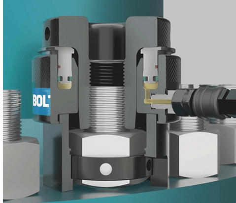
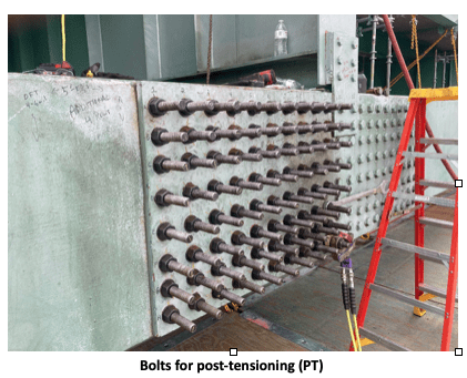
[li]3,000 bolts for the post-tensioning (PT) arrived Wednesday. Crews are replacing old with the new one by one.[/li]
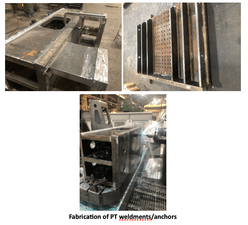
[li]The PT weldments/anchors, fabricated by G&G Steel out of Russellville, AL, will be delivered this weekend.[/li]
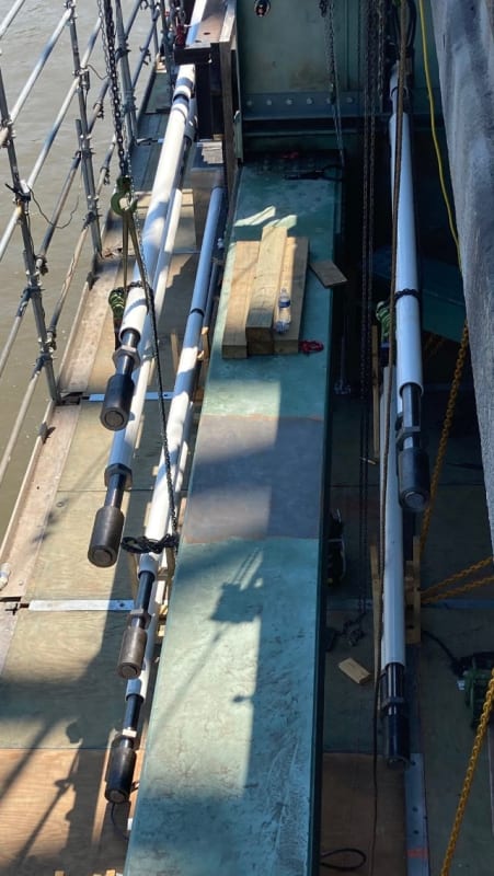
[li]The PT rods are being fabricated. The first shipment is expected Monday, 6/14.[/li]
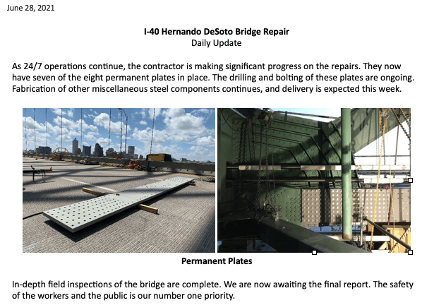
[li]Steel strengthening plates and splice plates for the permanent repair are also being fabricated. No timeline yet for delivery.[/li]
[/ul]
Construction work expected through the weekend:
[ul]
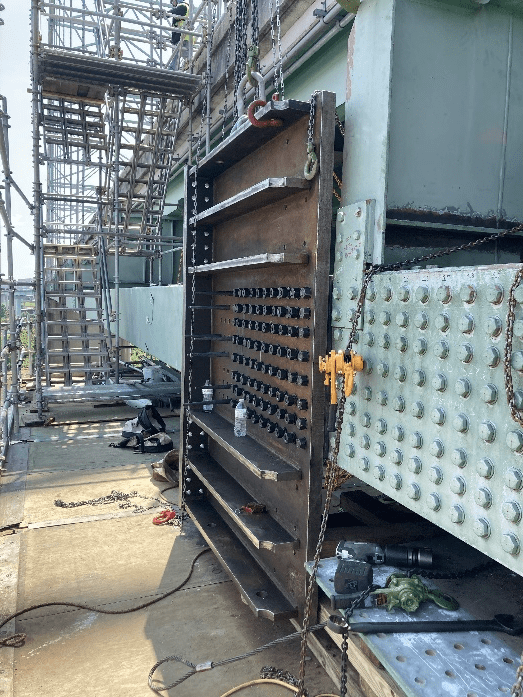
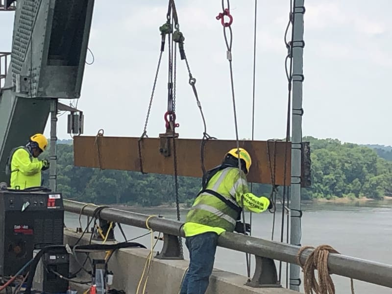
[li]Hang additional rigging for Phase II work[/li]
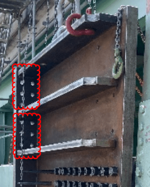
[li]Finish miscellaneous steel removal for PT and Phase II work[/li]
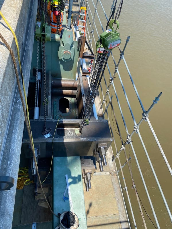
[li]Attachment of PT anchors/weldments to the tie-beam[/li]
[li]Hang PT rod supports from floor beams in preparation for PT rod delivery on Monday[/li]
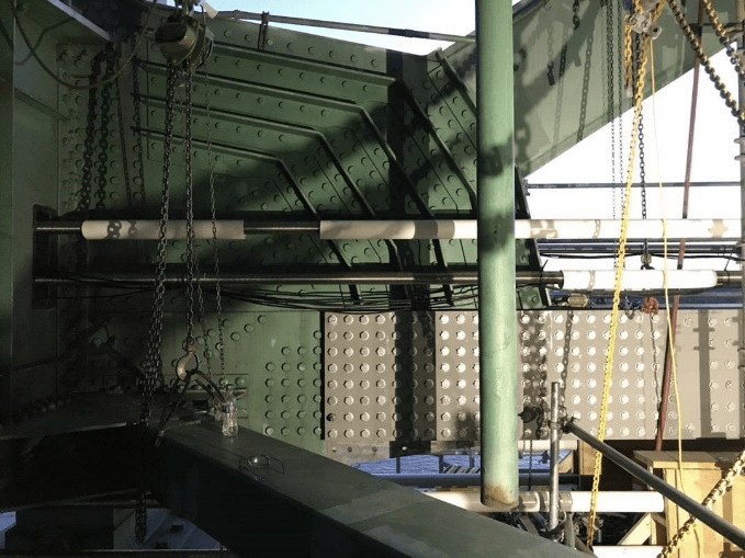
[li]Install Lower PT supports and protection on the platform[/li]
[li]Cut holes in floor beams for PT rods[/li]
[li]Remove and replace stiffeners at floor beams[/li]
[/ul]
Screen_Shot_2021-06-11_at_6.04.14_PM_o9fc83.png

Screen_Shot_2021-06-11_at_6.04.28_PM_sf3zdc.png
 
It is interesting that with each 3" dia PT bar I was expecting each to pass through the bearing plate, however, based upon the photo they must be terminating the 3" dia PT bar before the bearing plate and transferring to a 6 bar/bolt yoke connection for preloading etc.

Screenshot_2021-06-14_105012_hxmbu8.png
 
Tdot posted a picture on twitter today that shows the PT bars being installed, you can now see how they are transferring the load to the previously installed weldments.

E4LpfMxWEAQ7PtI_h0gfic.jpg

E4LpfM1X0AABUuR_tih76f.jpg
 
Update today, and a picture of the failure area:

Screen_Shot_2021-06-21_at_4.42.28_PM_qoog7o.png


Here's a slightly bigger view of the fracture area picture, scraped from the Word doc. Does the fellow inside have to run the plasma cutter???

failure_phv7wc.png


Link
 
∧ Note the curved cut traced out for specimen "2B"; they must think there's still load flowing through that inboard plate, and so do I.

Based on the photos posted by IRstuff above on that weld seam split, and the photos of the rest of the crack, I'm thinking the tie never had its load significantly relieved. Methinks <15% was redistributed.
 
When the span expands and contracts due to temperature changes, does it push the piers back and forth slightly or will there be some type of sliding or rolling support to accommodate expansion/contraction cycles?
Could an issue with either the design or maintenance of that support led to the excess tension on the tie beam?

Bill
--------------------
Ohm's law
Not just a good idea;
It's the LAW!
 
waross, the answer is probably both, and that's covered pretty well in the Structural Health Monitoring Paper (link above in post by 3DDave).

a pdf on the retrofit which shows some of the post-retrofit bearings:
[URL unfurl="true"]https://cdn.trccompanies.com/legacy/images/121-Schamber.pdf[/url]

The original design would have had some form of rockers or sliders to accommodate the length variation. It would be interesting to see if the new bearings had a higher friction load as compared to the prior arrangement but I have not found details on the prior bearings to compare to.
 
Anyone know what the tie load would have been? The SHM paper leads me to think it's nominally around 6000kip per tie.

So then is the 3000kip post-tension load on the rods meant to take just half the load off the damaged member? I suppose that is a possibility.
 
Status
Not open for further replies.
Back
Top