Continue to Site

Eng-Tips is the largest engineering community on the Internet

Intelligent Work Forums for Engineering Professionals

  • Congratulations KootK on being selected by the Eng-Tips community for having the most helpful posts in the forums last week. Way to Go!

Hernando de Soto Bridge (I-40 Mephis) 19

Status
Not open for further replies.

human909

Structural
Mar 19, 2018
1,932
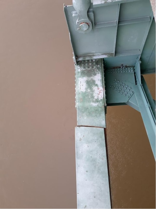
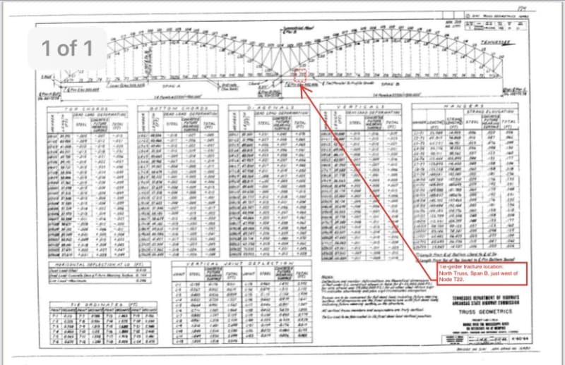
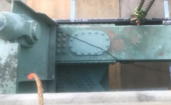
Some pretty serious looking issues here.
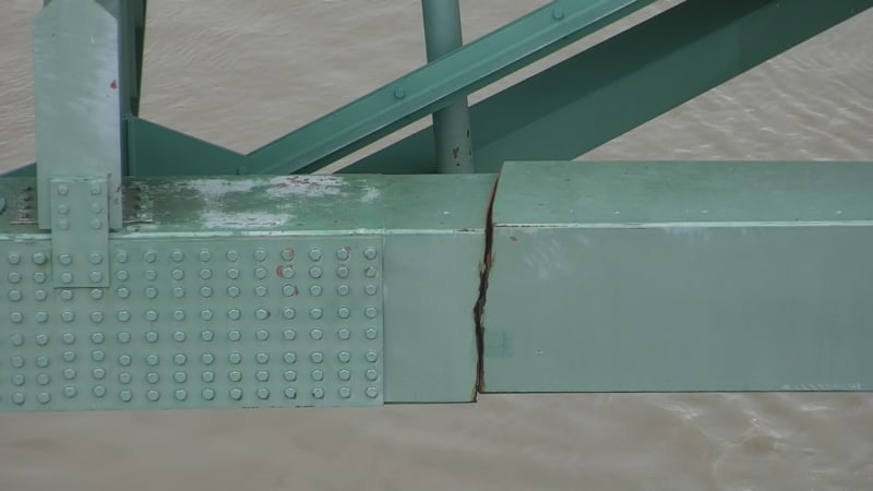
E1NBBdtXsAQ_Xpa_em0owc.jpg

E1NBBduWEAIJnA8_n4vt58.jpg

E1NBBduXsAAqN1p_pg4s4e.jpg
 
Replies continue below

Recommended for you

Thanks Craig Neth.

20,000 lb makes more sense compared to 20,000 ton. Still, very 'beefy' PT brackets!!
 
In addition to repairing the failed piece, determining the root cause is of equal importance, and if it is due to overstress due to passage of overweight vehicles, the state will need to pretend that they will do a better job at ensuring the max permitted axle load is nhot exceeded. Perhaps a review of past permits that had allowed overweight vehicles to pass and a review of bypass routes that truckers can use to avoid the weigh scales is also prudent.

"...when logic, and proportion, have fallen, sloppy dead..." Grace Slick
 
This ended up in my mail this morning and I don't know why... [Added] I suspect I know why... just my interest... did not know the poster, but responded that I would put the info on Eng-Tips.


noted in FHWA Technical Advisory T5140.4 (1), “…the tied arch structure…is one of the most nonredundant structures, relying entirely on the capability of two tie girders to accommodate the total thrust imposed by the arch ribs.”

Rather than think climate change and the corona virus as science, think of it as the wrath of God. Feel any better?

-Dik
 
The links which dik posted address lack of redundancy in tied arch bridges. But there is a distinction between the arch consisting of a single member vs. a truss. The bridge in this thread had substantial redundancy by truss action.
 
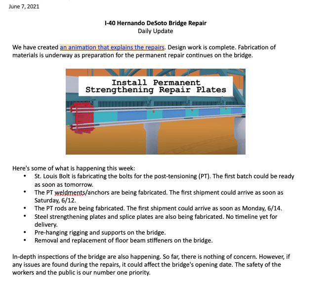
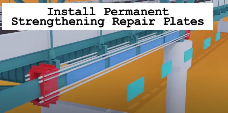
So the video posted by TDOT shows how the bridge will be temporarily supported to allow access for repairs. How the 'permanent strengthening repair plates' are to be employed remains a mystery.

Brad Waybright

The more you know, the more you know you don't know.
 
That's some funky music alright.

So it looks like they are adding extra steel plates in between all the existing bolted connections and then adding a further plate to bridge around the bolted sections.

Nothing about removing the damaged section or even sealing it.

Remember - More details = better answers
Also: If you get a response it's polite to respond to it.
 
LittleInch is correct. It's easier to see the pieces if you step through the fast animation.
bridge_va4b59.jpg

 
Still not much detail there. If that animation is to scale (probably not) it looks like the first set of plates actually overlaps part of the bolted node connection next to the failure. Then, the second set of plates overlap each end of the first. That would leave a gap between the new repair plates and the original steel and connections. That would certainly not lend itself to assisting with ongoing maintenance operations. Also, not able to determine if this stuff is bolted in place or welded. I'm not a civil, bridge, or structural guy, but it really looks like a patch job to me. I hope there's more detail to come out soon to change my mind.

Brad Waybright

The more you know, the more you know you don't know.
 
Retiredat46 said:
Three thousand bolts are required per June 04, 2021 release.
I'm guessing everything is bolted then.[bigglasses]

Brad Waybright

The more you know, the more you know you don't know.
 
Can anyone explain why they need to remove and then reinstall the "floor beam stiffeners"?
 
I think they are connected to the inside of that member where repairs are required

Brad Waybright

The more you know, the more you know you don't know.
 
Yep, you can see the end of one here.
bridge2_yjxomi.jpg


Some slight mods will probably be required to reinstall them.
 
Are the permanent repair plates on both sides of the beam or only on the outboard side, as it appears in the video?
Do the repair plates compensate for the weakened top/bottom sides of the original beam? I can see where the top outboard joint is rusting, near the break.

TTFN (ta ta for now)
I can do absolutely anything. I'm an expert! faq731-376 forum1529 Entire Forum list
 
So, the nuts on the ends of the 3" diameter PT rods are going to be like 6" across, How are they going to tighten them to get the tension needed? Is it like a 10' long box wrench?

TTFN (ta ta for now)
I can do absolutely anything. I'm an expert! faq731-376 forum1529 Entire Forum list
 
IRstuff-
They have me wondering about all of that too. I'd like to see the repair plan.

Brad Waybright

The more you know, the more you know you don't know.
 
Hydraulic jacks are non trivially big for something like 1000 ton, >20 diameter and about 3 ft tall
So a couple of those and some sort of yoke for all 8 PT rods at the same time?

TTFN (ta ta for now)
I can do absolutely anything. I'm an expert! faq731-376 forum1529 Entire Forum list
 
I don't think they would want to depend on just one jack for such an important operation, and a yoke would rival the PT weldments in size/complexity.
 
Status
Not open for further replies.

Part and Inventory Search

Sponsor