Continue to Site

Eng-Tips is the largest engineering community on the Internet

Intelligent Work Forums for Engineering Professionals

  • Congratulations GregLocock on being selected by the Eng-Tips community for having the most helpful posts in the forums last week. Way to Go!

Hernando de Soto Bridge (I-40 Mephis) 19

Status
Not open for further replies.

human909

Structural
Mar 19, 2018
2,008
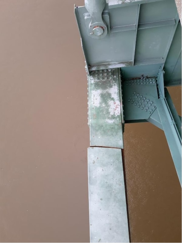
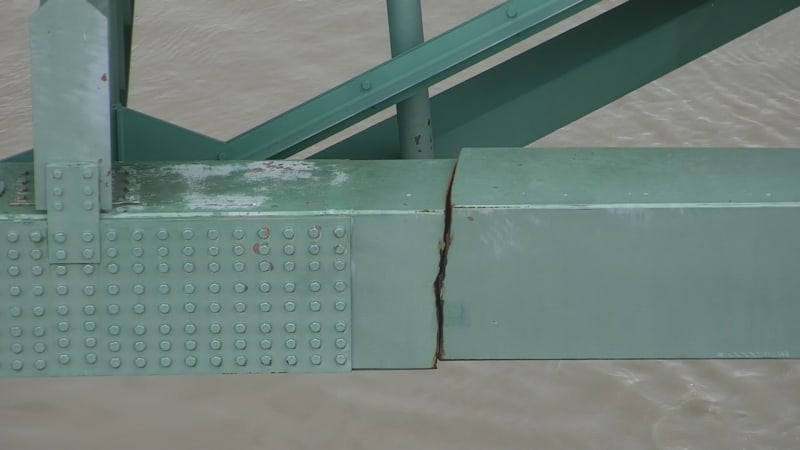
Some pretty serious looking issues here.

E1NBBdtXsAQ_Xpa_em0owc.jpg

E1NBBduWEAIJnA8_n4vt58.jpg

E1NBBduXsAAqN1p_pg4s4e.jpg
 
Replies continue below

Recommended for you

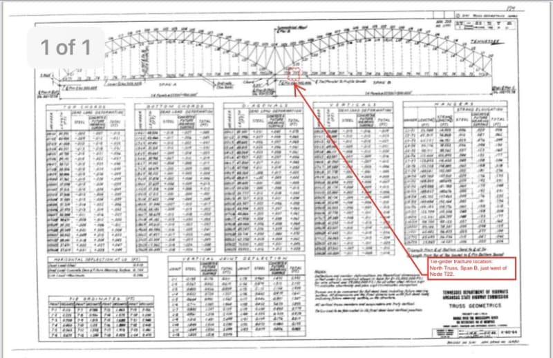
I am wondering how they captured the fracture without interrupting the node connections just adjacent to the repair.
pic2_nwww3d.jpg
pic3_eppkid.jpg
pic4_ixncu5.jpg


Brad Waybright

The more you know, the more you know you don't know.
 
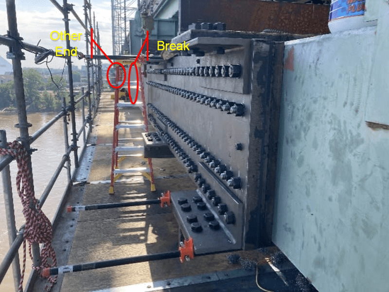
My thought now is that this plate does not span the damaged area. Are these fixtures, installed adjacent to each side for connection of members to stabilize the area to be cut out and repaired afterward?
pic1_lvvx4y.png

Brad Waybright

The more you know, the more you know you don't know.
 
The plate does span the damaged area; the repair plate looks to be about 30 feet long, the bolted section in the foreground is about 10 ft from the break, and the bolted section on the other end of the repair plate is on the other (left) side of the plate that's adjacent to the break.

Something like this:
plagte_twjvnx.png

plate2_pa8e6q.png

TTFN (ta ta for now)
I can do absolutely anything. I'm an expert! faq731-376 forum1529 Entire Forum list
 
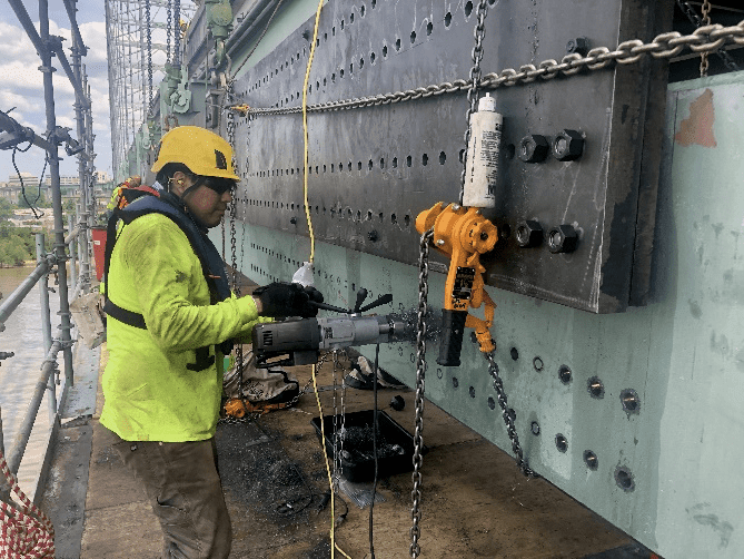
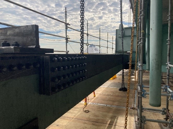
Assuming this spans the break, then the original splice plate was removed to allow this to sit flat against the existing surface. I can't see a way that the bolt holes in the new plate would align with the existing arrangement of 8 rows from the original plate. Maybe it's just an illusion.

Brad Waybright

The more you know, the more you know you don't know.
 
Looks like they've spaced the main plate out away from the surface of the box and it spans across that node.

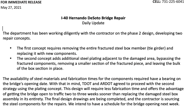
What are they going to do? Cut out the old box beam and field weld in a new section?
 
It appears the plate is at least 2 layers, I expect so that the bolted area can be against the original member while the single layer is spaced out enough it clears the existing splice plates. That'd explain why it's so thick. The part that is hard to understand is how they will replace the existing tie member with this plate installed. They'll have to replace the other adjacent tie too which they've drilled all the holes into. Maybe this is simply a splice to ensure the bridge stays up until they get the permanent fix figured out.
 
It seems that eventually they'll have to disassemble that node, at least in part. It wouldn't be possible if the bolts are covered by this temporary plate.

Brad Waybright

The more you know, the more you know you don't know.
 
I think LionelHutz and I were typing at the same time.[bigsmile]

Brad Waybright

The more you know, the more you know you don't know.
 
That picture is quite fun.

I counted at least the same number of people leaning over the bridge rail as there are people doing something below.

Spot the ventilation tube going into the void space. Some pooor small and thin bastard is in there holding a spanner and fitting nuts to studs...

why not just cut out the damaged bit and weld in a new box section??

Remember - More details = better answers
Also: If you get a response it's polite to respond to it.
 
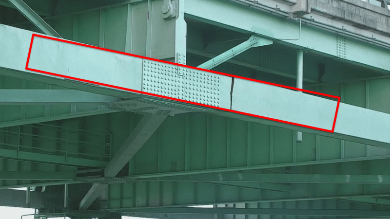
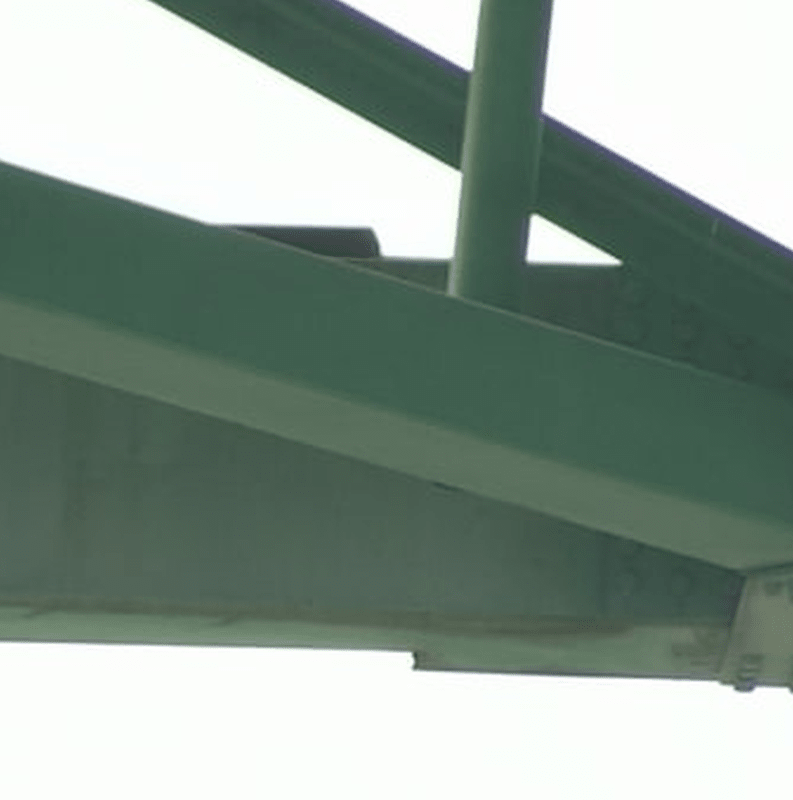
I don't think there's a crack on the inboard side; previous photos show that there's a partial crack on the bottom, and full cracks on the outboard and top. It appears that they cut through the webbing of the vertical support near the crack to get the mending plate through to the other side, but they couldn't cut the horizontal strut attached at that point, which is why the inboard plate is only about half as tall as the outboard plate, which covers the full height of the box beam.
crack_enz32g.png


TTFN (ta ta for now)
I can do absolutely anything. I'm an expert! faq731-376 forum1529 Entire Forum list
 
Somewhere on the Tennessee DOT page described the failure as a complete fracture of both sides and top, and 20% of the bottom.

Brad Waybright

The more you know, the more you know you don't know.
 
With the gap opened on the outboard side of the beam it is likely the inboard side is elastically twisted and bent. This is the natural result of tension loading an asymmetrical cross section.

<Speculation> the repair will require replacing the beam - drilled per the original dimensions. To install, the existing beam will be removed, and the load transferred to some sort of jig. </Speculation>

No small design problem.
 
Wouldn't it have been easier, quicker, and just as effective to remove the bolts from one end of the plates joining the two tie beams, and install the repair plates from that point out past the crack? Those bolts aren't holding much now. Doing it that way would avoid compromising the strength of the good tie beam with all the new holes.

Extending the repair plates to the good tie beam didn't add anything. If the bolted joint at the end of the failed beam was good enough for the original build, it should be good enough for the repair. The spacer plates could have been much thinner since the nuts and bolts don't have to be cleared. It probably would have cut the added dead weight by more than half.
 
Status
Not open for further replies.

Part and Inventory Search

Sponsor