Continue to Site

Eng-Tips is the largest engineering community on the Internet

Intelligent Work Forums for Engineering Professionals

  • Congratulations GregLocock on being selected by the Eng-Tips community for having the most helpful posts in the forums last week. Way to Go!

Hernando de Soto Bridge (I-40 Mephis) 19

Status
Not open for further replies.

human909

Structural
Mar 19, 2018
2,008
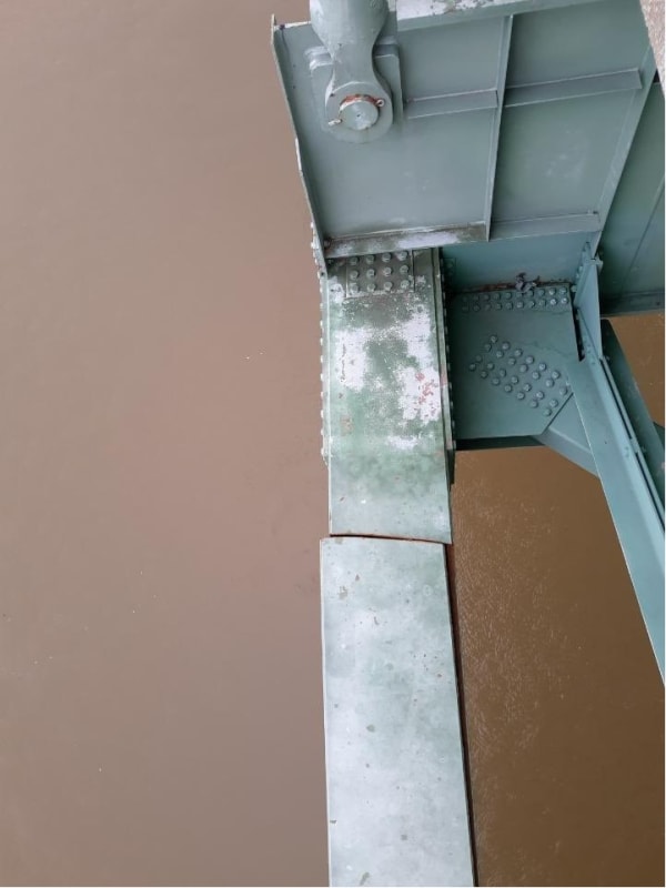
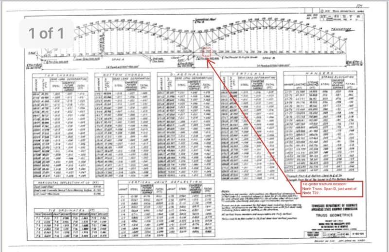
Some pretty serious looking issues here.
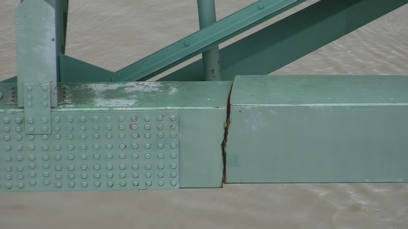
E1NBBdtXsAQ_Xpa_em0owc.jpg

E1NBBduWEAIJnA8_n4vt58.jpg

E1NBBduXsAAqN1p_pg4s4e.jpg
 
Replies continue below

Recommended for you

Might be a broken weld...

Rather than think climate change and the corona virus as science, think of it as the wrath of God. Feel any better?

-Dik
 
Is it possible to develop enough force to close that gap with post tensioning strands and jacks to allow the beam to be replaced?

Bill
--------------------
Ohm's law
Not just a good idea;
It's the LAW!
 
waross - that's a good question and I don't know. But if repairs are moving forward, I can only assume that either they can or that the locations the engineers expect the forces to transfer to can handle the additional loads. Maybe even a combo of the two.

dik - definitely could have stemmed from the box weld. I'm still thinking fatigue but we can both be right on this.

Box_Weld_Fatigue_s28nfz.jpg
 
I wonder if there is some sort of torsional stress that happens at this location. Like the wind is hitting the tie beam and cause some wind galloping, fluttering, or something and the beam is torsionally restrained at the connection. This cause some sort of torsional stress concentration, its not large but enough to become a fatigue issue.

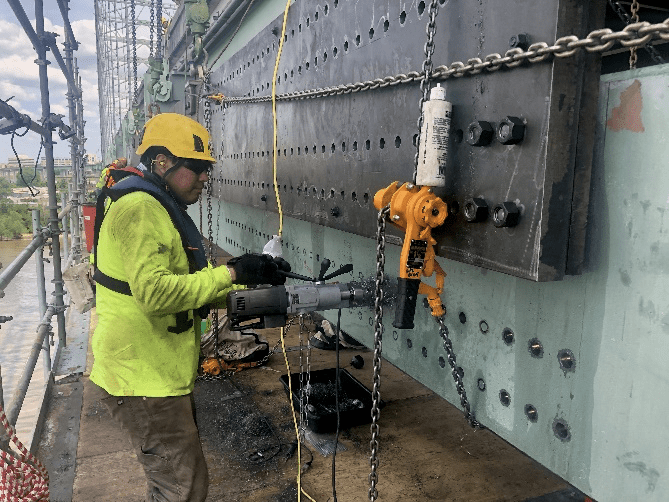
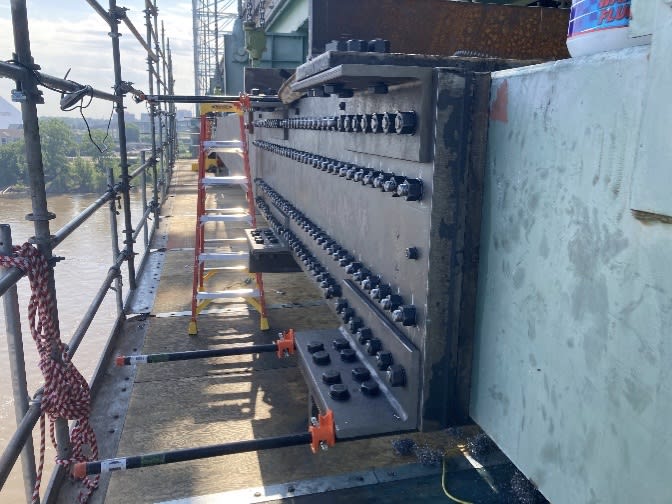
From the press conference, it appeared that the initial thoughts for the repair would be creating a collar and using tie bolts to pull the beam back together then welding the tie beam.
 
I seem to remember a conference FEA paper on a 4th or 5th torsional mode causing a tie failure in a offshore structure. It was also designed symmetry but ended up with unsymmetric loads.
 
Another possible asymmetrical loading scenario might be thermal expansion due to sun hitting only one side of the bridge? Would be interesting to see how that affects the member forces.

Also, in that bridge bearing study that someone linked to, they were seeing unexpected results during thermal expansion. They expected a build up of axial compression in the struts but weren't seeing it on one side of the bridge. They guessed it could be due to one of the piers tilting, but perhaps it had to do with this strut failing and redistributing the load into other members (that didn't have strain gauges).
 
Sounds sensible

Sorry I screwed up my bridge names It was the Kingston bridge that they have issues with. The M8 motorway goes over it everything blocks up at Anderson


To be quite honest with you, John, I have no idea... I think it could be 2 or 3 things, but would not be surprised if it were a 4th thing...

Rather than think climate change and the corona virus as science, think of it as the wrath of God. Feel any better?

-Dik
 
I have a gut feeling there is a materials factor in the mix as well. I would be wanting some sharpies and a hardness survey run up that box section before finalising the fix.
 
Truck weight limits were increased on the interstate system to 80,000 lbs in 1974. Arkansas was one of the states holding back on increased truck weights, only permitting heavier weights for a fee in 1983, completely accepting the full new 80,000 lb limit in 1986 after the trucking industry sued the state.

Link

The bridge was designed in the period prior to the increase in traffic weight. I also seem to recall that the bridge originally had fewer lanes. Is this another example of ever-creeping bridge use and load requirements leading to issues? Similar to some of the problems behind the Minneapolis I-35W Bridge Collapse (but the I-35W bridge also had an overlooked design flaw).
 
Two questions:
1. Are those strips backing strips for longitudinal welds?
2. Did those strips break or did they end there?
image_ckl5an.png


Bill
--------------------
Ohm's law
Not just a good idea;
It's the LAW!
 
I took them to be ribbing to stop hungry horse deformation. And that they broke with the fast fracture mode.
 
1. Are those strips backing strips for longitudinal welds?
Probably
2. Did those strips break or did they end there?
My opinion is that the weld crack propagated into the backer bar. The pieces of backer bar on the left are visible. The backer bar on the right id hidden by the camera position.

While welds are often made with backer bars, the design needs to consider these welds - just like all fillet welds have "crack like features" in the root of the weld. This sometimes drives a requirement to stress relieve beams when manufactured. If the situation can not tolerate weld root cracks, the backside gouging and welding is necessary, which probably can not be done in this case as the box is too small.

If the base metal is hot short it could also promote weld cracking. Hot short is possible even with a mill test report being to spec. Root cracks can also result from a welder having a bad day defect, and many other things.
WELD CRACKS, DEFINITIONS, CAUSES, PREVENTION & REPAIR

Members with a high proportion of alternating stress with respect to continuous stress are particularly prone to fatigue cracking. It is relatively easy to calculate the tension in the tie beams. It is significantly harder to quantify the variable load for fatigue calculations. Additionally in 1966 (a guess, based on the bridge opening in 1973) when the bridge was designed fatigue theory was not as well understood as it is now.

Here is a link to the Daily Update May 22, 2021.
 
Geez. Someone had to run calculations to include the weight of those plates in the dead load. [bigglasses]

Brad Waybright

The more you know, the more you know you don't know.
 
Unless the bolts pass all of the way through. That might explain the extra thickness in the plates.
 
The extra thickness can also be explained by needing to use the plate on hand that was thicker than the minimum required. The alternative might have been additional lead time.

Through bolts on a box girder splice would be a poor joint design. The squeezing forces would wind up stressing the box beam corners - which already are cracked.
 
Can you imagine being in that beam while someone with a 1" impact wrench is wailing away on the other end of the bolts?


I'm impressed that guy with the mag-drill could punch that many holes that line-up well enough to match all those plate holes.

Hey! How did they get the bridge beam re-aligned so holes could be accurately drilled? (chicken and the egg issue)

Can anyone see the crack? I can't see it in the work pictures.


Keith Cress
kcress -
 
Status
Not open for further replies.

Part and Inventory Search

Sponsor