Continue to Site

Eng-Tips is the largest engineering community on the Internet

Intelligent Work Forums for Engineering Professionals

  • Congratulations KootK on being selected by the Eng-Tips community for having the most helpful posts in the forums last week. Way to Go!

Locating Timing Pulley Tooth to Keyway 2

Status
Not open for further replies.

donatim24

Mechanical
Jun 13, 2018
27
I was looking at one of our drawings and we have a drawing for a timing pulley that requires the centerplane of a particular tooth to be aligned to the centerplane of a keyway within 0.5 degrees. Currently, the requirement is that the centerplane of the tooth is aligned to the keyway and not the surface of the tooth. I assume this is because the tooth form and size are controlled by the selected profile for the timing pulley.

The tooth profile is AT10. Therefore, there are no opposing planes that can be used to derive a centerplane. Is there an established way to determine the plane, or is the dimensioning approach flawed?

Best approximation of the requirement:
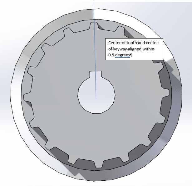
Timing_Pulley_Question_keaysf.png
 
Replies continue below

Recommended for you

An ASME Y14.5 "simultaneous requirement" of profile for the tooth and position for the keyway relative to the same datum reference frame could work, but I don't know how tight both tolerances should be to ensure a half-degree max. deviation.
 
Thanks, Burunduk. My question is more related to the practicality of measuring such a requirement. Is it even valid to reference a centerplane of a timing tooth, since there are no nominally parallel planes from which to derive the centerplane?
 
donatim24,

Your tooth is symmetric, right? The opposite faces of the tooth define a centre-line, and you can apply a positional tolerance. The only problem I see is the practical one of fixturing to the tooth.

--
JHG
 
It's a common practice in the manufacture of timing gears going back at least a century, started long before the invention of the feature control frame.

If the features do not share a common center then the angle is meaningless for timing. Typical gear tooth is specified at pitch diameter, but typically there is a depth at which the gear tooth width is determined so that width can be used as the basis for the center.

Cutting a mating groove in a plate with a slot to allow a screw to clamp tight seems like would work as a fixture on more than a single part. Plenty of other options - too many to bother with as I don't understand how this problem is seen as difficult.
 
Whether it's valid to "reference a centerplane of a timing tooth" depends on how exactly the datum feature is called out. In principle, you can use a feature of any shape as a datum feature.

One way to avoid the center plane datum that needs to be derived from the tooth, is a simultaneous requirement, as I mentioned. The tooth is profiled and the keyway is positioned to the same references in the same order, and that aligns them. That would be the first method I'd consider, but the alignment variation would accumulate both tolerances.

Another way that might be easier than a datum from the tooth is a datum from the keyway. The tooth designed centered on the keyway would be profiled relative to a datum reference frame that uses a center plane related to the keyway.


We use the Tooth space width, or thickness that is defined by the spline or gear data. This is taken at the pitch diameter.
 
Does a simultaneous profile control allow for a purely angular variation between the two features?
 
3DDave said:
Does a simultaneous profile control allow for a purely angular variation between the two features?

Check the figure in the Y14.5's datum reference frames section that shows a shaft with the 2 keyways. That example and the related text paragraphs should answer all questions on angular variations under simultaneous requirements.
 
Have not seen a profile callout with a limit on the number of degrees of angular rotation in it. Have you a figure that shows such a callout? Are there cases where the profile tolerance zone is allowed to change based changing radius? I know you can spend the money and increase production cost by using overly expensive callouts, but they aren't required for this.

Also, the simultaneous profile control is between features; the DRF is arbitrary.

 
"Angular" variation should not always mean a tolerance specified in angular units (such as degrees). What are the units for "Angularity"?

What do you mean by a "simultaneous profile control" and how does it relate to my suggestion of position for the keyway and profile for the tooth?


In this case the tolerance is specified in angular units, so it should mean using angular units in this case.

"What are the units for "Angularity"?"

Great question. What did you read about them in the standard?
 
This background may be helpful. The current dimensioning scheme is based off an angular tolerance with no GD&T applied. Our supplier can't seem to hit the tolerance, and I'm wondering if there is something wrong with our callout. I'm trying to think of a better way to express the fact that the design intent is that the centerline of the keyway and the centerline of the tooth are colinear. Whether that solution comes through GD&T or some other method is fine with me. If I were to take a GD&T approach, I agree that making the keyway a datum and positioning the tooth (either the surface or the centerline, I'd lean toward the centerline) is the way to go.

Thanks all for your feedback on how to fixture a gear tooth for inspection. That was very helpful.
 
What is your supplier doing to either inspect or manufacture the feature. You have nearly a 1 degree wide tolerance zone, which is sloppy for gear work. Did they express any opinion about the requirement before they accepted a contract to make these?

Also, how big are these - not familiar with "AT10" is that a gear tooth form or a belt interface? I could look it up, but it's your gears.

If it is your requirement, what did you have in mind to inspect and accept them - fixturing and measurements - and does the supplier know that thinking?
 
Controlling important rotational relationships by tolerance in angular units is rarely a good idea. The tolerance zone is often ambiguous, and when it's not, it doesn't make sense as it grows with the increase of distance from the vertex. Even if that is for some reason acceptable, the value to be reported is not clear unless the measured elements are of perfect form.

3DDave said:
Great question
And a rhetoric one.

donatim24 said:
If I were to take a GD&T approach, I agree that making the keyway a datum and positioning the tooth (either the surface or the centerline, I'd lean toward the centerline) is the way to go.

I'd choose to control the surface by profile, because of the shape of the tooth. It isn't defined how to obtain a center plane for position evaluation for anything but a simple tab or slot with opposed nominally parallel surfaces.
 
"Seriously?" - Yes. And the explanation is right there.
 
Unlike the edge case that is the bogeyman specter of the angularity group, there is no reduction to zero for a timing gear, so no ambiguity. Since the gear tooth is designed in response to distance from vertex, that's not a factor. The value reported is sufficient for purpose as the necessary form of the gear tooth is far more precise than the angular tolerance requires in its determination.

Anyway "rarely a good idea" in the face that engines are run on angular timing seems like a lack of knowing how things actually work.

As the radius drops to zero a fixed width tolerance allows infinite angular variation. Seems ambiguous in performance, but is really good for the CMM operator.
 
Further on alignment - wheel toe, caster, and camber - demand makers and service workers convert the values into a profile tolerance or you will abandon the car with them and never get into a car again. Angle encoders? Rip them out. Crank angle reluctors? Cut the wires to the sensor. Clearly torque+turn installed fasteners must be replaced with profile tolerance controlled installation.

What happens when angle measures are eliminated?
 
Hi, 3DDave:

Unit of angularity tolerances per ASME Y14.5-2018 is linear length (in. or mm). That is because Cartesian coordinate system is used on most of CMM machines. If you don't like this unit of angularity tolerance, you can create your own standard based on Polar coordinate system. CMM machines using Polar coordinate system are not as popular as the ones based on Cartesian coordinate system.

Best regards,

Alex
 
Status
Not open for further replies.

Part and Inventory Search

Sponsor