Continue to Site

Eng-Tips is the largest engineering community on the Internet

Intelligent Work Forums for Engineering Professionals

  • Congratulations KootK on being selected by the Eng-Tips community for having the most helpful posts in the forums last week. Way to Go!

Miami Beach, Champlain Towers South apartment building collapse, Part 15 32

Replies continue below

Recommended for you

Lionel,

What is your reality? Whether that truck is a 1500 or 2500, it is still significantly heavier than the average small auto, so a lot more load capacity next to I14.1. If Diesel Engine next to column then definitely more weight than a gas engine....

2500's are typically longer than 1500's by foot or so. That truck looks very long to me, and if someone took dimensions from that column to planter wall, and looked up spec on GM trucks, they could determine if 1500 or 2500.

I reference the 'Fly splat' the auto next to the truck made on it, when it slid into the truck during the collapse. Sorry Sym P. le for reusing, but I loved that analogy!

 
AusTony2046 (Electrical) said:
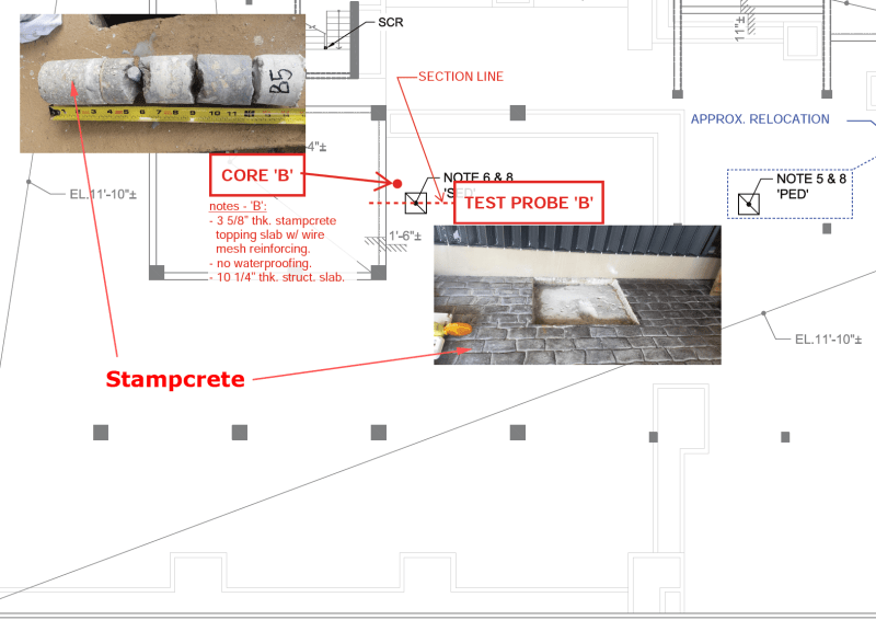
OT, what is "stamped" concrete and how does it differ from the concrete under the pool deck?

AusTony, both the stamped concrete topping slab and the patio deck pavers are finish floor materials and NOT structural members, like the 9.5" or 10-1/4” structural slabs below patio deck and parking deck.

We know waterproofing was not in original build under either topping material, but we know it was added under patio deck over pavers.

The poured stamped concrete slab was most likely poured directly on top of structural slab without any water proofing layer at all.
 
The reality is that there was a diagram which illustrated how the deck could have pulled away from the wall. Parlaying that into a complete theory that explains how the building must have collapsed starting at a pickup truck has no basis in reality. But, as I already posted there has been enough wild theory chasing already that has been claimed to be provable that I wouldn't expect it to stop now.

From what I see in the pictures, all I would conclude is that there is probably something under the collapsed deck holding up the deck under the middle of the truck. The pictures show nothing that could prove where the collapse started. It could have just as easily ended up like that with the collapse starting from the right side of the diagram.
 
Lionel,

I agree something under slab could be holding partial areas up, however I have not seen any other pictures where structural slab had the break features that IanCA has pointed out in this area. In other words I don't think deck falling on car, broke the deck.

We are talking a weakened slab ready to go at any minute with the slightest nude. The truck is just double the live load in that parking spot than the average small car would be, so a little more load on the camel's back.

As far as truck, what we need to know is if that truck was parked there the day before or was that the first time it was parked there. I don't see IanCA saying truck is the cause, clearly it is one of the point or distributed loads in his diagram of loads in that area. He was just trying to estimate the total load on the structural slab in a static condition.

What is your theory for the collapse?
 

The hood scoop indicates Duramax, the width of the rear passenger door indicates crew cab and the front grill indicates High Country trim, at least to the best of my Googling ability. That is to say, a 6000lb vehicle or two modest vehicles parked atop each other sans bug splat.

I agree that all should be mindful not to extrapolate extraordinary theories from generalized photographic evidence.

P.S. Googling is a term covered by spellcheck.
 
AusTony2046 said:
OT, what is "stamped" concrete and how does it differ from the concrete under the pool deck?
Hello @AusTony2046,

Following on from thermopile's post above, there are good images in the 2020-10-14 Board of Directors minutes approved, uploaded here by SFCharlie (Computer)(OP)7 Sep 21 16:29

Link

It is worth looking at the original document, specifically page 43 of 83, because the images embedded are high resolution and you can copy and paste into any image processing application then zoom in.
ParkingDeckStampcreteWithoutWaterproofing-notes_y3k8fa.png


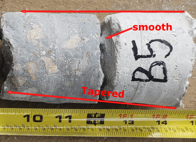
The image of Core B, and notes below it, confirm there was no waterproofing on the parking deck. Something doesn't seem right to me about the last piece on the right labeled B5, it appears to be tapered, the top surface looks smooth and the color appears different than the section above. But the fact that the deck had delaminated meant that the yield strength of the connection of the rebar to the concrete was substantially reduced below its design value, right?
Core-B5-notes_aal7bu.png
 
AusTony2046 said:
Well, it was dark, and looking straight down on a scene where not much horizontal shift had occurred, it might not be obvious from above that anything had happened directly below.

Good point, I completely agree.
 
thermopile said:
Or was stamped concrete pushed up in accordance with IanCA's planter fail diagram?
@thermopile I believe that the displacement of the stamped concrete you mention agrees with the idea of the initial failure occurring at the connection of the parking deck to the southern wall.

LionelHutz said:
That piece was pushed up by the column that punched through. Trying to apply more meaning to that seems like a fruitless endeavor.
@LionelHutz Please refer back to the post by Sym P. le (Mechanical) on 2 Feb 22 21:07 and the annotated image of the southern wall. If zone A begins to fail before zone B then at some point in time zone A will be lower than zone B, but they are somewhat connected, certainly through the pool deck gate, and columns in zone C have not yet punched through. The surface of the deck is retained in the East and inclined down in the East West direction (lower in the West) as well as being lower in the south. This would likely pull the deck (and stampcrete) on West side of the deck closer to the column as the deck rotates down. But the size of the section lifted really depends on where the stampcrete cracked.

In conclusion, I believe there is information there and it agrees with the failure modes being proposed.


LionelHutz said:
The pictures show nothing that could prove where the collapse started. It could have just as easily ended up like that with the collapse starting from the right side of the diagram.

@LionelHutz
Let's try to reach an agreement by considering the information presented so far. We can select two candidates for the initial point of failure and compare the likelihood that the selected region or point would lead to progressive failure and eventual collapse of the North-East portion of the tower. Let's compare the theory I am advocating, that the initial point of failure was the connection of the parking deck (zone A) to the southern perimeter wall, with the theory that the initial point of failure was column K13.1 punching through. I have attached a document with the comparison of the details as I understand them. Please feel free to correct any errors or add additional information I have missed.
 
thermopile said:
IanCA, your concrete deterioration along South wall due to pool chemicals is interesting as to why concrete at south wall perhaps failed from chemical reactions, and perhaps just let go of rebar at first.
I'm pleased to hear that. I will provide further information as time permits.

thermopile said:
BTW, I wish I had worded my radio silence better,
Your comment was completely reasonable and resonated with me. Over.

thermopile said:
I am not an expert in anything,
I think it helps to have a range of experience and exposure to different engineering and science disciplines. So you can be proud of that.

thermopile said:
I would like to add that frequency of sound determines transmission thru building materials, and that at lower frequencies standing waves can form that reinforce some frequencies and cancel some frequencies.

Lower frequencies transmit thru concrete type building materials better than higher frequencies.
Thanks for this input. This will come into play more when considering the effect of vibration caused by driving sheet pile.

thermopile said:
I am seeing tension reinforcement in bottom of 13” slab not lining up with tension rebar in bottom of 9-1/2” slab, and possibly a construction joint at slab transition.
I am not sure where the transition you are referring to is located, can you provide an image or drawing, please?

thermopile said:
I will just wait for your complete logic and evidence to flow.
I hope that the document I posted in response to LionelHutz will help to explain more of my thinking on this aspect. It was also written with you in mind.
CTS Initial Failure Compare Link
 

Reverse_Bias said:
Here is a view that shows the the entire part of the deck that detached from the wall.
@Reverse_Bias, Thanks for adding that image. It is very similar to the one by Chandan Khanna first published by the NY Times on 7/3/2021 archived here but the version you posted has a slightly better angle on the wall.
 
thermopile said:
if you zoom in on the passenger rear tire of the black pickup truck, from the image Reverse_Bias posted above, it sure looks like the deck is broken under planter wall in this area, and it appears passenger rear tire is in a deeper depression of the deck. Almost like the truck is loaded with bags of Sakcrete in the truck bed or something very heavy?
I agree, the rear wheel has dropped far enough to allow the deck to come into contact with the underside of the sill. I don't think there is additional weight, just that there was insufficient strength in the concrete deck, to the south, to support it.

thermopile said:
Truck also appears to be parked much closer to wall than surrounding autos? It was mentioned early on, that perhaps truck hit planter wall???
Agreed, more to follow.
 
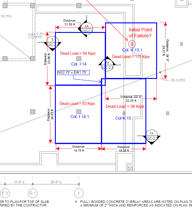
In trying to guess where the initial failure of the pool/parking deck happened, I like to consider which columns were most heavily loaded. Because of the spans, column K-13.1 appears to be the most heavily loaded by a long shot. It is almost 38% more loaded than I-14.1, about 36% more loaded than I-14 and about 17% more loaded than K-15. If we assume deterioration was roughly equal everywhere and barring meteorites, any theory about the initial point of collapse would have to explain why a more lightly loaded column would fail/punch through first. Not only is K-13.1 more heavily loaded than I-14 and I-14.1, but I-14&14.1 are bigger columns. Thus, I would think that gridline K was more likely as an initial point of failure than gridline I. Following is a diagram showing the tributary areas for each of the four columns:

Area_of_Influence_load_calculations_irhufy.png


Here are my rough calculations of the dead loads:

[URL unfurl="true"]https://res.cloudinary.com/engineering-com/image/upload/v1644099527/tips/Load_Calculations_ianneg.pdf[/url]

EDIT: There is an offset towards the west of 3.5 feet as you go south from column K13.1 to the one I have labeled as K15. So K15 is not on gridline K. This offset is labeled on Sheet S2 of 14 with the 1-17-80 revision of the original Breiterman drawings. These are the "Basement Level Dimensions." It should also be noted that gridline 15 is 8 inches south of gridline 14.1. There are a lot of offsets in the column spacing that are interesting and make calculations difficult.

The parking slab thickness of 10.25 inches that I used in the calculations is taken from a Morabito core. The change in dimension of the slab from the pool deck to the parking deck I haven't found in the original drawings. For calculations purposes, I have assumed that the slab changed from 10.25 inches to 9.5 inches along the north south gridline defined by the column I labeled as K 15, which is not on gridline K. It's a guess.
 
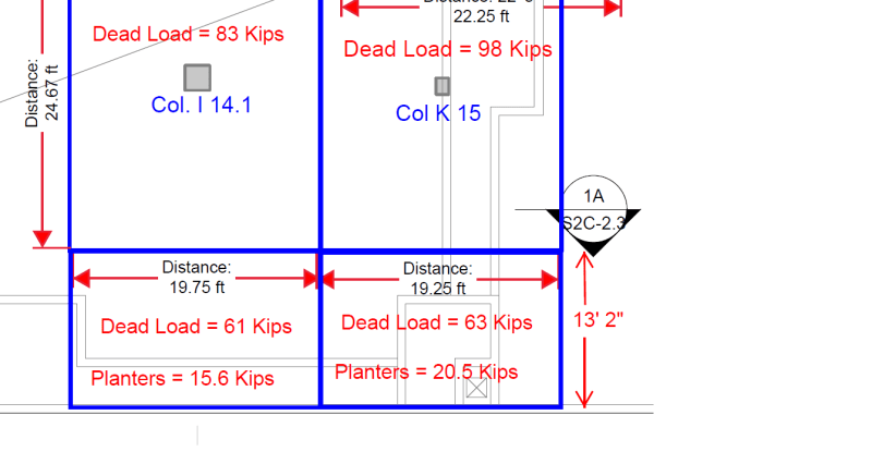
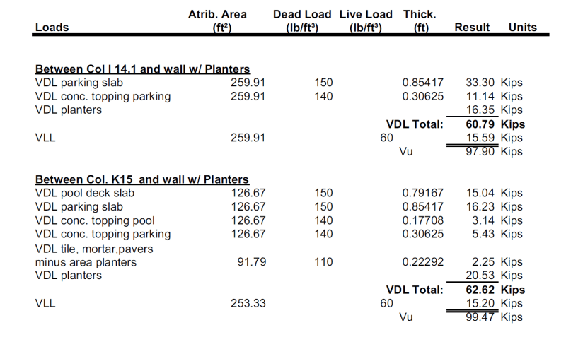
Following is a quick and dirty of the loads in the areas between the tributary areas for columns I-14.1 and K15 and the wall. The planter weight is included in the overall dead load. Most of the planter weight would be on the wall and thus not loading the slabs. I still don't see how the failure could have started at the wall.
Wall_loads_b41sw5.png


Rough calculations:

Load_calculations_for_wall_wry5lj.png
 
Sym P. le said:
Consideration for weight of vehicles?

That would be in the live load of 60 lbs per ft². I didn't include it in the diagram, since the live load would be even everywhere but it can be seen in the calculations. The factored load uses 20% for the dead loads and 60% for the live loads.
 
IanCA,

Thanks for your responses to my questions/thoughts out loud. I just got back to read your white paper comparing two theories. The longer lever/moment arm tugging at 1’6” step down in building slab is interesting concept. I am having hard time visualizing how the slab punch shears progress. The long lever arm indicates at some point in time, the deck has punched thru all deck columns prior to hitting garage floor, such that at some moment in time, the whole deck is tugging at I/K/l/M 9.1 at same time. That implies deck failure at South Wall progresses East-West prior to the wave going South to North.

Perhaps I am not following your logic correctly?
 
@thermopile - I don't see any reason the deck would be high in that area unless something is holding it up. Skyhook I suppose?

@IanCA - It seems pretty clear to me that the piece circled was lifted in the corner by that column which punched through.
 
Lionel, I am not disagreeing with you about something being under the slab on North side of break. Per IanCA’s drawing there are two tension breaks in slab in that area. One on top and one on bottom. Question is did those breaks occur before slab landing on garage floor, or after part of slab landed on say an auto below, with the breaks occurring from a cantilever situation?
 
Status
Not open for further replies.

Part and Inventory Search

Sponsor