Continue to Site

Eng-Tips is the largest engineering community on the Internet

Intelligent Work Forums for Engineering Professionals

  • Congratulations KootK on being selected by the Eng-Tips community for having the most helpful posts in the forums last week. Way to Go!

Miami Beach, Champlain Towers South apartment building collapse, Part 16 24

Status
Not open for further replies.

dik

Structural
Apr 13, 2001
25,673
thread815-484587
thread815-484717
thread815-484915
thread815-485059
thread815-485171
thread815-485223
thread815-485379
thread815-485535
thread815-485637
thread815-485844
thread815-486084
thread815-486593
thread815-487022
thread815-488247
thread815-489644

Rather than think climate change and the corona virus as science, think of it as the wrath of God. Feel any better?

-Dik
 
Replies continue below

Recommended for you

Sym P. le now that I have watched the BI video you linked, do I understand your post from 15 May 22 21:16. The pool of water at the base of column 76 is clearly there. To those not aware of the signs of failure this just looks like a damp column!
 
It's possible that as the 76/slab connection deteriorates, the low point of the deck shifts to the north.

Bread_Crumbs_e2gwxs.gif
 
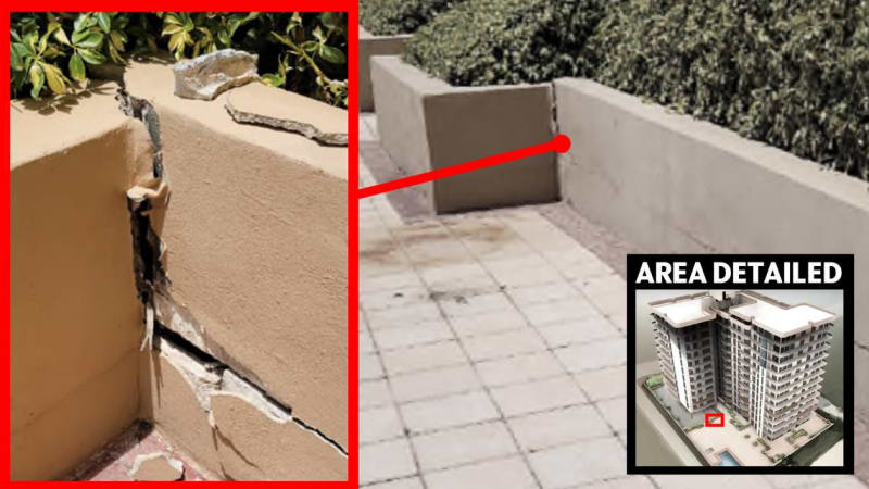
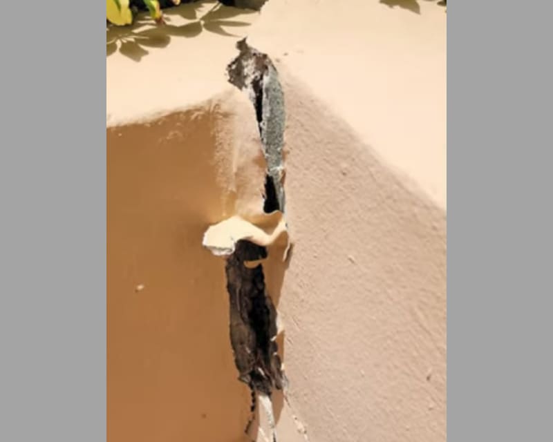
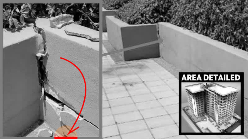
When I look at the picture of the crack, I don't see any crack in the deck. It seems if the section on the left (in the photo) dropped, there would have been a crack in the deck, too. If you argue that the whole deck dropped down (along with that section of the planter), thus eliminating a crack in that area, what caused to top of the planter wall to refuse to drop with everything else? That isn't just a horizontal crack, that's an opening of about an inch.

How can the deck and part of the planter fall downwards, but leave the upper part of that planter wall behind?


spsalso
 
The structural slab is buried in a topping layer (varying thickness to provide slope and drainage at time of placement) and deck tile. This will redistribute and disguise structural deficiencies in the slab (as seen from above).

It appears that there is a course of cmu's capped by concrete, or the upper layers of cmu's have longitudinal reinforcement. Either way, it's obvious that it has longitudinal rigidity that spans high/low points in the deck deflections. Apparently, the reinforcement did not extend around the corner.

edit: Longitudinal reinforcement may have been required so that the planter contents don't push out the walls.
 
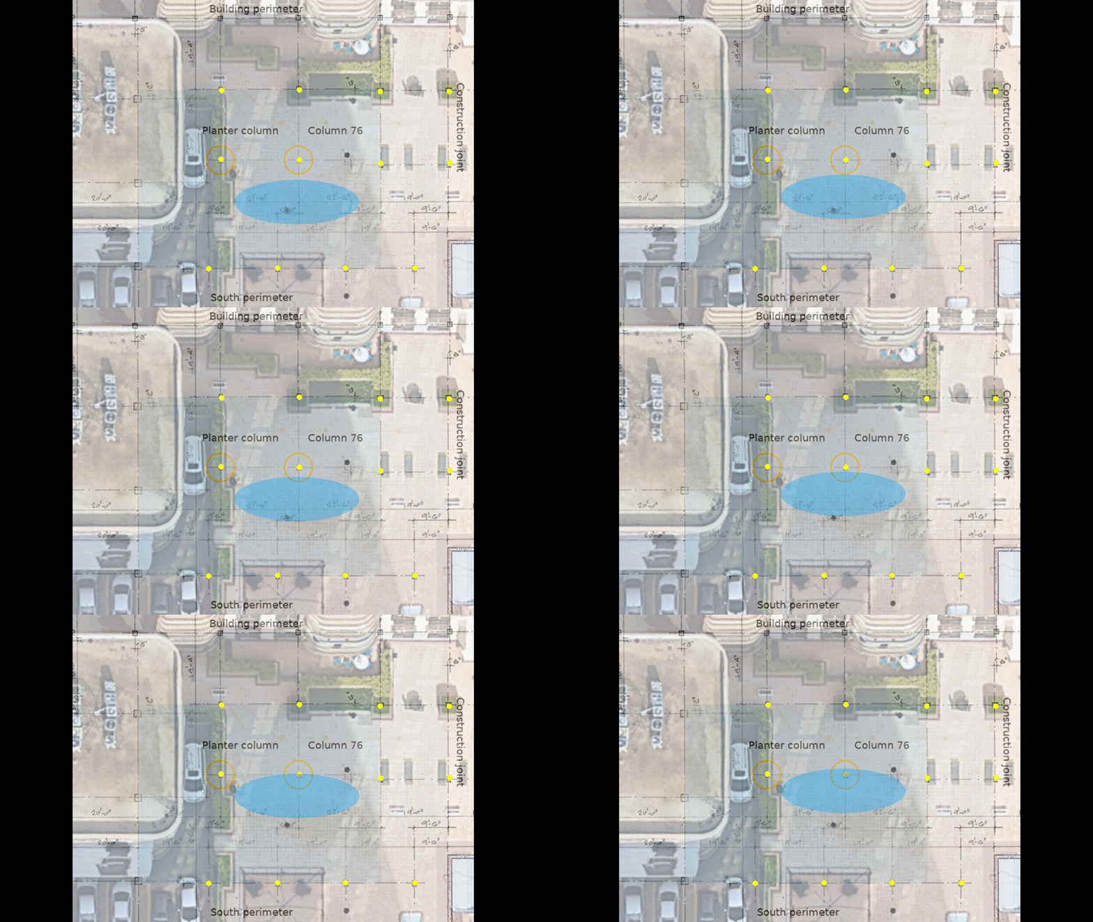
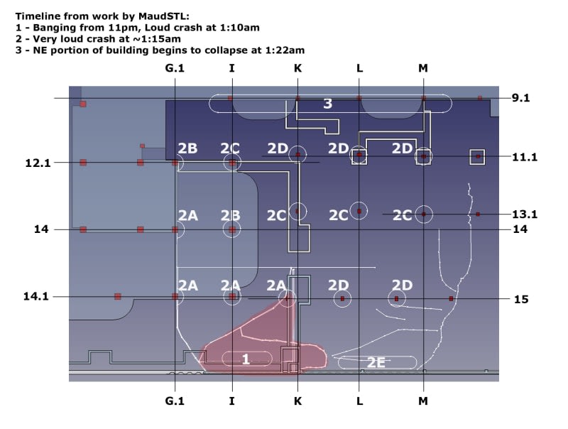
I would like to understand more fully the crack progression mapped by IanCA, married up with Sym P. le's overlay animation.

EDIT: I am not implying anything right or wrong about IanCA's theoretical sequence, rather would like this crack layout information added to Sym P le's animation.

Edit 2: If you look at Green/Yellow/Red Sag Diagram posted by Reversebias, clearly there is a large area of red sagged area along the South Wall after corrosion factored in. The only way I can see that much sag at the south wall is if the concrete/rebar has sheared from the wall connection in that area which would shift stresses to the South, East and West.

Edit 3: Or the foundation supporting the south wall had settled in relation to the interior columns.


sequence-column-refs-2_f76gwt_gjvhr1.jpg
 
"The structural slab is buried in a topping layer (varying thickness to provide slope and drainage at time of placement) and deck tile. This will redistribute and disguise structural deficiencies in the slab (as seen from above).

OK. So the slab drops, but somehow leaves the decking in position (leaving a void)--there seems to be no damage to the decking (see, for example, the "area detail" shot that shows the joints between the two walls and the decking). But the wall on the left is still neatly connect to that decking, as is the bottom of the wall on the right. So that would imply it stayed with the decking instead of dropping with the slab. But then the upper part of the wall on the right would somehow have to have raised itself up an inch to make the crack.

It appears that there is a course of cmu's capped by concrete, or the upper layers of cmu's have longitudinal reinforcement. Either way, it's obvious that it has longitudinal rigidity that spans high/low points in the deck deflections. Apparently, the reinforcement did not extend around the corner.

We don't see evidence of any deck deflections. It all looks nice and neat-ish, and pretty well connected to the bottoms of the two walls.

edit: Longitudinal reinforcement may have been required so that the planter contents don't push out the walls.

And that needed reinforcement would have been in the horizontal plane, not the vertical."


spsalso
 
In light of the new evidence recently presented, if I was the engineer and had requested pictures of the cracked planter box, I would have also wanted to get pictures from the opposite side of the planter box as well as from down below. Was there any damage to the side of this planter box facing the parking area? Does the lack of expected pictures imply a lack of damage or a lack of concern?

Was the planter box fractured by the column breaking an inch through the concrete slab and into the CMU but being held and supported by the rebar alone at that time? If that is the case, then it makes some sense that the planter box may not have fractured on the side facing the parking area so no need for photos. That could also mean that more catenary forces were being applied to the deck for a longer time period than what we have been thinking.


[sub]
[/sub]​
 
Nukeman948 (Electrical) 17 May 22 00:50 said:
... the column breaking an inch through the concrete slab and into the CMU ...

The column is not doing a stabbing movement. It's the slab falling down around the column "as though it was punched". The planter merely remains in place atop the column/slab shim until it looses any semblance of stability as the wider remaining structure drops out from under it. The slab section south of the column is showing greater downward movement which would be consistent with failure of the slab/column connection being initiated at the south edge of the column where the stress is greater from the 30' span.
 

The displacement in the corner of the planter is not representative of the movement everywhere else. I would read that corner as an indicator of displacement but would exercise caution on what it means. The upper corner of the planter wall being perpendicular to the structural member of interest would exaggerate any gaps due to slope changes in the slab. The vertical drop on the south side of the column is very real and and given the columns proximity to the corner (which is a low traffic area) the aggregate of all the materials may just be floating over a discontinuity in the slab and waiting for a good thump.

Regarding planter wall reinforcement, although a primary benefit in this case may be for horizontal reinforcement, a simple lintel reinforcement scheme would benefit in both directions.

Really, I don't have all the answers, I just hope I'm right enough to be able to defend my posts. Thanks for the feedback.
 

I've made more than a few posts debunking the Miami Herald's analysis. For instance, the graphic you posted starts with edge conditions which include the slab along the south perimeter dropping 1" in an undamaged state. That just doesn't make any sense. That's not to say that punch out doesn't happen, it's just that their graphics are way off. A better analysis would have been to examine progression given slab punch out at the most stressed column/slab connections, which are easily determined, and the results would have been more interesting in areas they highlighted. I think the Miami Herald was trying to sensationalize the impact on CTS of the work on the neighbouring property and as a result did the discussion a disservice.
 
Looking at the crack in the planter situation:

The slab drops.

What does it take with it?

It can't be the "return" wall (the one on the left of the picture), because the slab would have pulled it through the decking (which, it has been argued, separated from the slab), and there would have been a crack between the decking and that wall.

It can't be the bottom of the long wall, because there also was not crack generated when that part was pulled past the decking. The detail photo shows the two walls meeting at the deck, without any apparent damage at all.

That leaves us with a slab that fell, leaving the decking and those two parts of the wall in place. AND the top part of the right wall, which decided to jump upwards. By about an inch. Because it was in the mood?

I do believe that is a correct description. Am I missing something?


spsalso
 

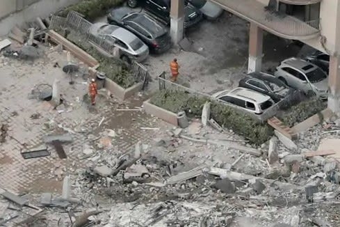
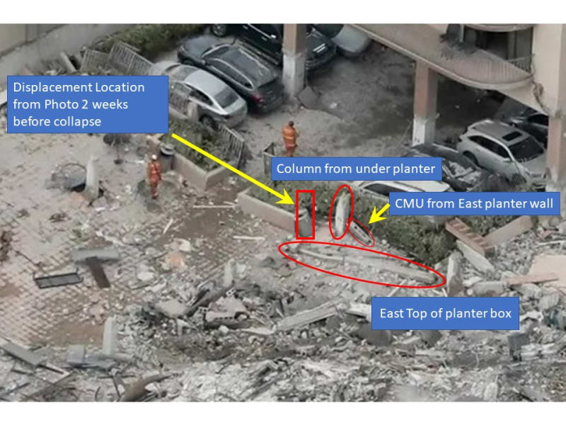
I had to download the file before I realized what it was you were getting at --> Column_came_though_planter_box_AP_Building_Collapse_Miami.jpg

As I stated earlier, the column didn't go through anything, everything else fell down around the column.

Perhaps they should rename this failure mode "falldown" as opposed to "punchout" but that would just confuse everything else.
 

Possibly, there is differential movement between components that the imagery isn't tuned to convey. We don't know the time stamps (day?) on the various images either.

Differential_Movement_flvxns.jpg
 

Though I don't see the point, I tried to do an overlay but just seemed to make a mess. You are welcome to mark up my images and show your results.
 
I'm just thinking with this new imagery, it's like interviewing Moses after crossing the Red Sea and not mentioning that the sea parted.

Moses: "We just did it"

Reporter: "And you're not even wet!"

Moses: shrug

 
Sym P. Le said:
It appears that there is a course of cmu's capped by concrete, or the upper layers of cmu's have longitudinal reinforcement. Either way, it's obvious that it has longitudinal rigidity that spans high/low points in the deck deflections. Apparently, the reinforcement did not extend around the corner.

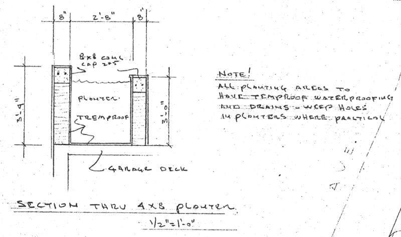
I think you are correct Sym P. Le. Here is a sectional elevation of the planter from the 1979 drawing set, showing an 8x8" concrete cap with 2 x #5 bars:

Planter-sectional-elevation-1979-plans-p40-of-336_wqxtbr.png


I think that detail was drawn with the southern wall in mind, but I imagine it was applied to other planters and explains the longitudinal rigidity you describe.
 
Status
Not open for further replies.

Part and Inventory Search

Sponsor