Continue to Site

Eng-Tips is the largest engineering community on the Internet

Intelligent Work Forums for Engineering Professionals

  • Congratulations KootK on being selected by the Eng-Tips community for having the most helpful posts in the forums last week. Way to Go!

Miami Beach, Champlain Towers South apartment building collapse, Part 18 30

Status
Not open for further replies.

SFCharlie

Computer
Apr 27, 2018
925
Replies continue below

Recommended for you

When witnesses described vehicles descending into an abyss (my words for dramatic effect), we can't be certain they went all the way down in one shot. The evidence does support that the failing deck pulled hard at the south perimeter wall and it would seem that it consequently pulled hard at the north building perimeter as well. I think the slab rebar would be the force conveyance more than the topping mesh. I refer you back to my blue coloured plan which shows the bulls eye impact of the documented evidence which is also consistent with edge to edge diaphragm failure.
 
Yeah. I see it says the mesh constitutes additional positive moment reinforcement after negative reinforcement generally fails, "giving way to a type of cable". It just seems like there is an emphasis on it. Maybe I read to much into it. It not helping anyway. Could it be a critical piece in the progression? And the mesh was an added design feature not documented? Still, the "remaining" steel behaves differently as it progresses is the main point. Its function is altered. The mechanism that began the progression is not the mechanism that took over.
 
I don't agree with everything they state however I find their discussion generally to be helpful. There is no evidence presented that the topping mesh was installed with sufficient overlap to aid in a cable effect and it is applied to the wrong surface for positive moment reinforcing.

The slab/column connection at 76 was the first to exhibit negative bar failure yet this did not result in an instant progressive collapse. The connection at the planter column also exhibited the same type of failure and again an immediate progression did not ensue. These two failures did however create a load redistribution and set up the eventual catastrophic outcome. This is why I was looking for the "final straw" which of itself may not have flashed through the entire deck. The stall 135 rebar was likely taking considerable abuse from the load redistribution and could have suffered from corrosion as well. The idea that the slab hung like a cable from edge to edge is a distinct possibility but I won't be putting any money on a blanket description of this disaster.
 
Sym P. le (Mechanical) said:
it is applied to the wrong surface for positive moment reinforcing.

I was struggling with that as a read it. I think what he is saying the mesh adds to the positive bars that remain in terms of forming a cable. and not that the mesh constitutes positive reinforcement. I read it wrong and stated it wrong. That is clearly my mistake. My bad. I apologize.
 
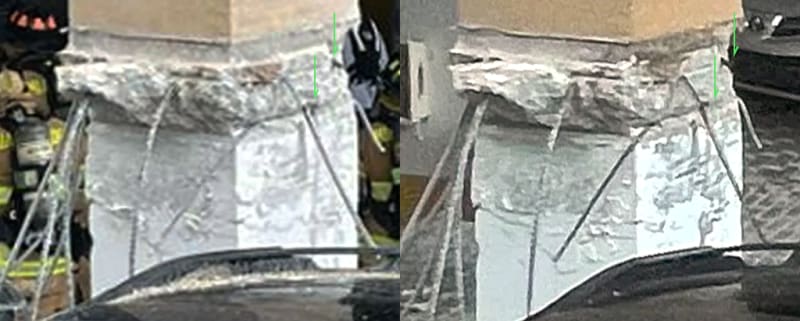
The following 3D is difficult to view (I had to manipulate one image substantially) but it shows the two rebar stubs below stall 135. I believe these are the only photos of broken rebar but this cannot lead to a conclusion that they are the only broken rebar. It will be interesting to see what evidence was collected by investigators in this regard.

The topping layer and tile would mask a lot of deck upper surface cracking and shifting that occurred leading up to the collapse. For example, the tile at column 76 did not appear to shift when that connection deteriorated and the tile near the planter column was in far better shape than the planter would indicate when that connection deteriorated.

Witnesses heard significant unexplained banging at various times prior to the collapse and this could be the breaking of rebar or as other evidence might indicate, a de-laminated slab loosing its grip on the rebar. Am I correct in thinking the broken rebar leads the failure and the other rebar gets pulled out?

3D_Rebar_Stub_dfja4g.jpg


Another column with a lower mat consisting of a single strand of rebar along the column center line (though running N/S instead of E/W)
Lower_Mat_One_Rebar.02_ghuzxu.jpg
 
In today's (5/5/2023) New York Times, there is an article discussing the building failures in the recent earthquake in Turkey.

If you're able to access it, it is certainly interesting.

I mention it here because there appear to me to be certain similarities with the causes of the failure of this building. An added penthouse and do-it-yourself inspections, for example.

I believe there's a comment by the writer that things like the Turkish building failures don't happen in the US.


spsalso
 
I'm not sure where to start on that one. I skimmed it mostly. But I saw them talking about soil conditions and supporting a mid rise and nothing about piles. Am I missing something?
 
...it shows the two rebar stubs below stall 135.

Thanks very much for posting these close-up images.

I'm interested to understand whether there is general agreement within the fields of structural engineering or building failure analysis about the marks [Edit: and shape of the remains of the deck] left on columns by decks when they fail by punching shear and how they can be interpreted to indicate the bending moments acting on the deck at the time of failure and movement of the deck immediately after failure. Specifically, if the deck to one side of the column begins to fail first, where do the marks appear on the column?

Can anyone here comment on that aspect, please?
 
Shouldn’t there be a NIST update meeting soon? What’s going on?
 
Right that’s what I checked. I paid attention to that meeting and expected then to announce another meeting but haven’t seen anything.
 
Sym P. le said:
Check out this article which I referred to earlier.

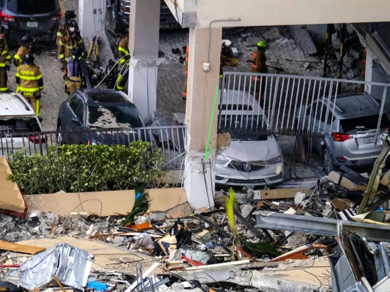
Thanks very much, I have read both versions and they are helpful. They do show in Fig. 1 view AA the expected shape of the deck remnants on the column if the deck fails due to punching shear and the load and bending moments are symmetrical and positive, but to me, the deck remnant on column I14.1 (stall 135) on the north side of the column appears to be inverted, please see the image below, suggesting to me that the deck north of the column was experiencing a negative bending moment and the south face was experiencing a positive bending moment.
Column-I14.1-from-west_ogimyz.png

I acknowledge that the north side looks more rounded in some other images.

The description by Ernesto Valdes of the punching shear failure of the columns in axis I attributes the failure to increase in vertical load due to the preceding failure of the deck at column K14.1, however, the area of failure on the east face of column I14.1 appears to be nearly vertical and flush suggesting to me that unbalanced bending moments from east to west were not as high as unbalanced bending moments from north to south.

Thanks for preparing the 3D image pairs I did finally get that to work for me by concentrating on aligning the arrows.
 
My basic thoughts of the two broken stubs are that they are evidence of generalized slab punch out to the east of the column, the same area compromised by failures of the now infamous Planter column and column 76 slab connections. They are, in fact, the smoking gun being sought to sum up the general speculation that we are left to. Hopefully more answers will be forthcoming with detailed engineering analysis and presentation.

I can't find any adequately detailed photos of the column immediately east of stall 135 (that would be K14.1) to see what it may reveal. Though vehicle traffic may have aggravated the decay, I now think it more likely that a drooping slab broke these two rebar. There was an extended period of audible warnings as the structure succumbed to decay but it was not understood. Just as the decay at column 76 did not leave concrete chunks on the parkade floor, it is now apparent that this type of indicator would not be forthcoming and explains why visitors could drive into the parkade minutes before the collapse and not see anything of concern.
 
Sym P. le said:
I can't find any adequately detailed photos of the column immediately east of stall 135
Thanks very much for looking.
 
NIST said:
NATIONAL CONSTRUCTION SAFETY TEAM ADVISORY COMMITTEE (NCSTAC) MEETING
June 14-15, 2023

June 15, 2023
Time (ET)_______________Topic___________________________________Discussion Leader
11:25 am - 11:45 am _____Presentation of Champlain Towers South: _____David Goodwin
|_______________________Failure Hypotheses______________________Project Leader, Champlain Towers
|_______________________________________________________________South NCST
|_______________________________________________________________NIST
|_______________________________________________________________Kamel Saldi
|_______________________________________________________________Project leader, Champlain Towers
|_______________________________________________________________SouthNCST
|_______________________________________________________________NIST
|_______________________________________________________________Judith Mitrani-Reiser
|_______________________________________________________________Jack Moehle
|_______________________________________________________________Project Leader, Champlain Towers
|_______________________________________________________________South NCST
|_______________________________________________________________James Harris
|_______________________________________________________________Project Leader, Champlain Towers
|_______________________________________________________________SouthNCST
Edit: emphasis Sp. David Goodwin
 
Status
Not open for further replies.

Part and Inventory Search

Sponsor