Eng-Tips is the largest engineering community on the Internet

Intelligent Work Forums for Engineering Professionals

  • Congratulations waross on being selected by the Tek-Tips community for having the most helpful posts in the forums last week. Way to Go!

Miami Pedestrian Bridge, Part IV 74

Status
Not open for further replies.
appster said:
They announced that de-tensioning had been completed at the other end and one rod on the North; were working on the last bar when the failure occurred.

You will notice at the other end of the bridge the bottom deck continues all the way to the outside far face of the vertical member giving more concrete pull out capacity as well as engaging potentially more PT tendons in the process. This would explain potentially.


I have felt for some time that there might be other detail differences at the ends which saved the South end from failing first, or there was some difference in the PT stress or procedure at each end. Voids in the concrete due to compaction differences or areas being affected by ducts or drains may also be different.

Shadows shown in the progressive collapse shots indicate that it was a bright sunny day, the cars are not casting long shadows east or west so the the sun is almost straight up; the canopy would therefore be at a higher average temperature than the web or bottom flange adding some added thrust to the end diagonals as it tries to expand. De-tensioning of 2 was carried out earlier in the day when the temperature was cooler and the canopy not shading the web so effectively.

A later post indicates that the depth of member 2 was increased leading to a much longer footprint for 2 meeting the deck at such a flat angle. This longer footprint gives more shear area at the deck to transfer its compression load into the deck and also brings more tension strands in the deck into effect in resisting the tension in the deck from the compression in 2. Major difference between North and South end to explain why south end did not fail first.


pontduvin said:
tension in the bar would create shear friction, a clamping action tending to keep the two interfaces in contact. If the bar was detensioned, this would tend to reduce the shear friction and increase the likelihood of failure.
That thought crossed my mind too, especially that loosening could precipitate the failure. But much depends on the positioning of the PT rod endplate, the angle relative to the crack/joint, etc. My sketch was only meant to illustrate the idea that changes on the PT rod could be somehow correlate to the time of failure. Likely the endplate and the crack/joint would not be exactly where I showed, especially of #12 got pushed out right to its bottom.
 
jrs87 said:
I would not be surprised if NTSB builds a physical copy of 12-11-deck portion in their lab.

From NTSB website: Link

NTSB said:
While segments of the bridge are being transported to and stored at an FDOT facility, there are no plans to reconstruct the bridge as part of the NTSB investigation into why the bridge collapsed. The nature of the structure and the way it failed make reconstruction impractical.

Although the NTSB state "no plans to reconstruct the bridge" this does not rule out a small scale joint segment for testing...but I doubt they will. Time will tell.
 
Ingenuity said:
Quote (jrs87) I would not be surprised if NTSB builds a physical copy of 12-11-deck portion in their lab.

Would I be right in thinking that an early NTSB task would be to identify whether the fault lies primarily in the (computer) model, or in the physical construction? I'm thinking that NTSB can presumably get hold of the model that FIGG used, and test it using same or different software, applying a creative range of test conditions to identify vulnerabilities etc. Is that a relatively quick and low-investment task?
 
Some excellent theorising here and well done to all those keeping this on an engineering level backed up by good graphics and use of photos.

My take now is definitely moving towards movement of some sort of the base of 11/12 being the root start point, but less than 0.5 seconds is brutal to determine cause and effect. Given that this was essentially a rigid structure, even a small movement of column 11 ( 10,20,30mm??) would surely lead to a large movement of loads onto other parts of the structure not designed for it, leading to failure. The key part for me was realising that the top tendon in column 11 is intact and clearly anchored into the base of column 12 and survived more or less intact. The lower tendon which ripped out of no 11 was anchored into the slab somehow and hence tension on it was providing some of the anchoring / shear resistance to the base of 11/12 as postulated above. Once the tension was released a bit it transferred load onto other reinforcement / tendons which couldn't cope.

One thing maybe to throw into the debate is whether as the bottom tendon in no 11 was released as we believe it was or could be, this then would add to the load on the inner two tendons in the base slab as noted by sheerforeceeng. Could the item seen on the left of the video screen grabs by ingenuity actually be one or both of those inner tendons breaking off? Remember at the start that prior to the collapse, some "twanging / bull whip cracking" noise were heard by a member of the public as he went underneath he structure waiting for the stop light. Was that one of the strands in an over worked tendon snapping?

We have no visibility of the end of the bottom slab at that point as it collapsed right next to the pillar so until it is lifted out of the way no way to say what the end of the bottom slab looks like and if all the tendon ends are still there.

The release of facts in the next couple of weeks hopefully by the NTSB will be very interesting.

Remember - More details = better answers
Also: If you get a response it's polite to respond to it.
 
Tension adjustment in No. 11

In the design drawings the collapsed bridge was supposed to be shifted by 4 transporters, 2 for each end. The two transporters at each end support the end bay. Thus No. 11 in the original design would have little load and only in compression. No PT was listed in the drawing.

In actual execution the end transporter was proved to be impractical and was shifted to the interior span. So the last bay at each end was free hanging and so No 11 would have to take 1/5 of the 950 tons dead weight (5 bays) and resisted pure tension.

It is possible that the PT was introduced to resist this changed condition.

Once in final position No. 11 would be in its highest compression and the tension in the PT is no longer required.

Logically the forces in the two PT ducts should be removed. Exactly how the tensile force, introduced in the construction sequence, was dealt with is not known to us yet. However if the tendons were tightened even slightly when No. 11 is already fully compressed a small axial shortening has to take place. The top canopy and the bottom walkway will have to be bent inward. This can initiate the failure of the connection at the bottom of No. 11 and 12 if it the point of the least resistance.
 
TheGreenLama said:
And in one of the earliest posted videos by Tomfh in Thread I, 18 Mar 2:42, member 12 actually looks, of all things, to be pulled inwards.

I think there may be some confusion over the motion of #12 because behind #12 there is a tree. As the vehicle and camera moves, due to changing perspective the tree moves rightward relative to #12 in the foreground, possibly making it look like #12 itself is moving.

Here's a frame from earlier in that video: , in which the tree in question can be seen to the left of #12.

gwfiu_20180324_dashcam_fahcf4.jpg
 
That computer animation showing the assembly of the FIU pedestrian bridge (Miami Herald) explained my question about how the transporter was positioned under the finished structure.
 
Ingenuity said:
Previous posts in PART I, II and III of this subject have asked about previous prestressed concrete truss bridges.

About 40 or so years back, I was at a presentation of a couple of new bridges under construction in Germany; one of them was the Bendorf Bridge, and, I don't recall the name of the second one. they were both post-tensioned using Dywidag threadbars... Rebar's cheap, but, the connectors aren't. One bridge went across a gorge and was supported on columns/piers that were several hundred feet high. Both were constructed using the 'backspan' to support 'flying' construction equipment. That's when I started using Dywidag for seriously loaded anchorage.

Dik
 
Regarding 11-12-deck, I wonder if a structural engineer might comment on how such joint systems work typically? What they might expect to see inside this bridge?

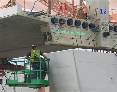
The ongoing discussion leads me and some other posters above to wonder how the design intends to route stress from #11 to the deck's tendons. For orientation, we're discussing this area:

gwfiu_20180324a_01_endofdeck_dty1fu.jpg


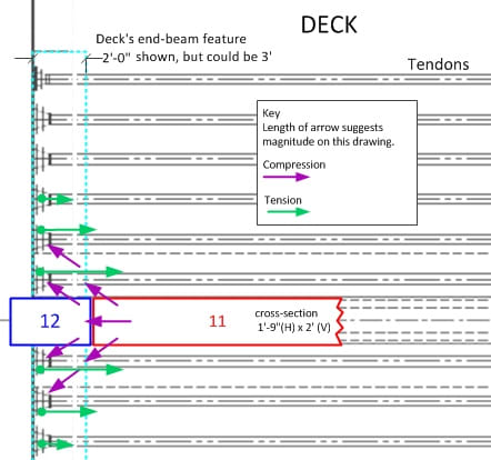
A naive first speculation might be like the picture (plan view) below, which troubles the mind because of its poor distribution of forces to the tendons. (I think SheerForceEng remarked on this):

gwfiu_20180324a_02_endofdeck_imypr2.jpg


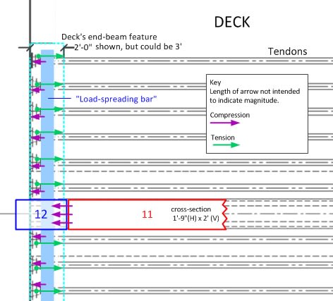
So perhaps the idea is like in the following image: #11 presses on the deck end beam, which in turn acts as (or contains) a very stiff bar distributing the horizontal load to the tendons. Is that feasible?

gwfiu_20180324a_03_endofdeck_kh6p4h.jpg


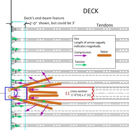
Or might the horizontal load from #11 be constrained by rebar that folds back south (rightward) into the deck for some distance: Either rebar in #11 folding like a hairpin under #11 into the deck, or L-shape rebar, with one leg vertical in #12, and a horizontal leg into the deck. Those horizontal legs in the deck could be long enough to spread compression broadly into the deck, to be resisted by the tendons?

gwfiu_20180324a_04_endofdeck_gadrr6.jpg


Might this last scheme, if a valid approach, correspond to the rebar seen at the left of the NTSB "rubble" photo earlier on this page, apparently torn out of #12?
 
Great schematics!

If shear failure at the ends of the structure was the cause, it seems that an approach more towards a solid web of the I-beam by both ends could have added some safety factor with little penalty regarding materials, weight and "aesthetics".

For example, another horizontal beam resting on the lower deck, with horizontal PT elements running between the low portion of the two last diagonal members of the web.
In other words, forming a self-supported triangle that liberates the end of the lower deck from additional tension and shear loads, as well as those diagonal members and their nodes from bending loads (element 10-horizontal beam-element 11 and element 2-horizontal beam-element 3 triangles).

"Where the spirit does not work with the hand, there is no art." - Leonardo da Vinci
 
Regarding the protrusion at the left end of the deck, shown in the time-lapse video right before the failure initiated, I think gwideman is correct, it is just the deck corner coming into view as the position of the camera continually changes position.

We know that lower PT bar in member 11 crossed the failure plane at the end of the deck because its anchorage remained in the deck section after the collapse, causing the bar to be ripped out of member 11 as it fell. This supports the theory that the horizontal failure plane was located somewhere near to that shown in gwideman's sketch.

It also appears that the deck section remained nearly intact after the collapse. This seems to imply that the longitudinal post-tensioning in the deck did not adequately participate in transferring the compression in member 11 to the deck.

The failure resembles a punching shear failure in a pile supported footing with no pile under the column, only in this case the column was at the edge of the footing. The only benefit of member 12, and the future pylon, in resisting shear failure, other than a bit of confining compression pressure on the joint, is that they necessitated the need for vertical mild reinforcement through the failure plane. But the contribution of this steel would be minimal until the bridge was completed.

It is unfortunate that a longitudinal PT strand was not positioned to run down the middle of the deck as this would have directly resisted the punching shear of number 11 transferring the load directly to the deck by confining the end of the girder with a PT anchorage plate. The location of the 8" deck drain may have prevented this...an unfortunate tail wagging the dog effect. This drain pipe also seems to have dictated the temporary bearing locations on top of the pier preventing a reaction point directly under member 11.

The devil is indeed in details, especially in a modern concrete bridge where member sizes are minimized using PT to reduce weight, and aesthetics drives compromises in the placement of structural elements. The deck section was relatively thin given the localized demand placed on it by member 11 at this stage of the construction.

Once completed this bridge failure most likely would not have happened, so the accelerated staged construction can be said to have played some role in the collapse, though this only points to the need to carefully analyze each construction stage to ensure life safety.

 
Any idea of why the top of this bridge was coloured with a dark blue? It's not visible from anywhere, except the air, and maybe adjacent tall buildings. White would be less likely to 'heat up' on sunny days.

Dik
 
Dik, that's just shadowing due to the depressed pan shape of the top chord at night. Other photos above show the surface was the same light-colored concrete as the rest of the bridge.
 
Thanks, gentlemen... Just noticed it on the picture posted above.

Dik
 
Pontduvin said:
It is unfortunate that a longitudinal PT strand was not positioned to run down the middle of the deck as this would have directly resisted the punching shear of number 11 transferring the load directly to the deck by confining the end of the girder with a PT anchorage plate. The location of the 8" deck drain may have prevented this...an unfortunate tail wagging the dog effect. This drain pipe also seems to have dictated the temporary bearing locations on top of the pier preventing a reaction point directly under member 11.

What would be the reason for the debilitating central location of the deck drain pipe, right on the plane of the web?

Is there any reason for the pitch of the deck not to drain towards both edges of the deck and then to collect the water by a low curb next to each edge and channel it out through two longitudinal pipes of smaller diameter, not interfering with the structural steel and PT cables?

Probably hard to get the proper pitch of any pipe in order to effectively and quickly drain at each end of this bridge if considerable span deflection existed.
If so, some accumulation of water could happen midspan, increasing weight on the deck.
This designed inward pitch could potentially add a considerable amount of water weight on the deck in case of drain clogging or hurricane type precipitation.

"Where the spirit does not work with the hand, there is no art." - Leonardo da Vinci
 
Take a look at the opp end. #2 appears to be a deeper member. Dashcam vid proves it took a licking and kept on ticking. In the prelim dwgs, it is same cs area as all the others. So, it appears someone ran the numbers again and decided to increase the area of #2 and not #11.
123_mzvpsn.jpg
 
appster said:
If your theory is correct then the structure should have failed at the opposite end where member 2 is at an even flatter slope.

If the preliminary drawing is accurate, unlike member 11, web member 2 (type B) was specified to have two permanent tensioner bars loaded at 200 KIPS each (please, refer to SheerForceEnd's post of 24 Mar 18 01:10 above).
To resist buckling under gravity of the more slender and horizontal member 2 perhaps?

That was specified prior the adjustments for transporting the structure while both ends where protuding beyond the jacks were made.
Those adjustments for temporarily resisting the negative moments (compression at the bottom of the I-beam and tension on the top) at both ends could have been adding two new tensioned rods to member 11 and increasing tension above the specified 200 KIPS in rods of member 2.

If that is true, tension for member 2 could have been only reduced, but keeping the specified values, which could have helped keeping the integrity of the lower node (end of slab, diagonal member 2, column 1) under shear and bending loads.
Perhaps the opposite end of the bridge (by member 11 and column 12) did not have that structural advantage if the directions were to release all the tension in both bars.

"Where the spirit does not work with the hand, there is no art." - Leonardo da Vinci
 
Status
Not open for further replies.
Back
Top