Eng-Tips is the largest engineering community on the Internet

Intelligent Work Forums for Engineering Professionals

Miami Pedestrian Bridge, Part V 71

Status
Not open for further replies.

dik

Structural
Apr 13, 2001
25,564
0
36
CA
This continues the discussion from Part I, II, III, and IV. Please read the other threads first:

Part I
thread815-436595
Part II
thread815-436699
Part III
thread815-436802
Part IV
thread815-436924
 
Replies continue below

Recommended for you

Just some thoughts on the design that might spur some thoughts by others.

The midspan chord forces of a truss can be estimated by simply dividing the moment caused by the end reaction at midspan by the depth of the truss. Assuming under dead load the resulting force in the lower deck would be resisted completely by the bottom slab post-tensioning so that the concrete stress in the concrete slab would be nearly zero, results in a significant amount of prestress. This prestress, or quite a bit of it, would need to be imparted into the slab prior to casting the diagonals and top slab otherwise the prestress would cause to much of a moment at the end of the span. This implies a cold joint between the diagonals and the top of the bottom slab.

The bridge code reduces the amount of shear friction that can be transmitted through a cold joint relative a monolithic joint. Therefore a cold joint requires more reinforcement to resist a potential shear friction failure at the join.

The vertical compression from the diagonal can be used to help resist a shear friction failure along the cold joint, but in the case of member 11, the horizontal force is larger and additional shear reinforcement is required. The contribution of the PT bars appears to have been limited so that a significant amount of mild reinforcement, fully developed on each side of the joint, would be needed.

There does not appear to have been much additional mild steel added.

The fact that the dead end of the lower PT bar in member 11 stayed with the bottom slab when it fell indicates that the failure plane was obviously above the anchorage. We don't know exactly where this anchorage was but it would have needed to be above the 8" drain pipe. This holds for the top dead end anchorage as well. These PT bars were not grouted and therefore would offer no dowel-action in resisting shear on the assumed failure plane (cold joint). If they crossed the failure plane, their stress component perpendicular to the failure plane would help clamp the joint together, while their tangential stress would tend to cause a shear friction failure. Again the angle is such that the latter would be dominant.

At this point it looks like member 11 could have failed at or near the deck surface taking out member 12 in the process. This would destroy the truss action and lead to failure.

If you compare the end diagonal connection of the FIU bridge to the end diagonal connection of a steel bridge, the former appears to have been under designed. There should have been PT bars or PT strand in the bottom slab, in-line with the diagonal on the centerline of the bridge, to transfer the horizontal force in member 11 into the bottom slab (chord) so that a less predictable mechanism such as shear friction would not need to be relied on. This was not a robustly designed bridge. It appears to have been designed in a way to speed construction, which can happen on design-build projects where the contractor has a significant role in managing the design details to aid construction.

The design was also meant to be innovative, pushing the boundary of normal practice. Engineering firms pride themselves in their ability to do this; it is a way of distinguishing themselves from others. There is nothing wrong with this as long as there is a significant amount of attention given to design and detailing, along with adequate oversight in the form of an independent design and detailing check by a competent engineering team, and peer review by a team of industry recognized experts to ensure that nothing is overlooked. This level of oversight would not be unusual for a project that sells itself as being innovative. It is what is required of such designs and seems to have been lacking on this project.
 
Archie264 said:
And equally interesting, in my opinion, to know what the design would have been had they used a fountain pen and a slide rule.

Yup... I still use 3D frame programs for analysing and use spreadsheets for design... don't have confidence in letting the machine do all the work. I've been using SMath Studio (free MathCAD like program) a lot these days, and, it sure beats a sliderule... and, it would have likely stood up... I was a bit curious how they managed the lateral stability issues with substantial unbalanced loading, and, if they used the cable stays to help.

Dik
 
Yep, a good sanity check. And I'm actually an HP RPN calculator guy, myself, (well, plus software) but I have to wonder if I wouldn't be better off if I used a slide rule. It'd sure force me to think about things more.
 
Gwideman said:
Going back to look at Tomfh's post of 18 Mar 18 02:49 (Part I), I see that is shows something different from the animation frames posted on Part IV by INCENTIVE at 24 Mar 18 01:34. I have never been clear whether there are one or two (or more) dashcam videos, so maybe that's part of the difference.

At any rate, here are frames from Tomfh's animation:


The feature circled in frame 1 looked to me like the north west corner of the deck, and I had dismissed it. Not sure why it disappears in frame 4.

But what I only now noticed is the bulge feature circled in frame 4 that enlarges in frame 5, and then appears to blur in frame 6. In the animation, this appears to coordinate with motion of member 11, and seems in line with 11. In short, looks like it could be 11+12 punching out the end of the deck. Too fuzzy to be 100% convincing though, of course.

I think the 'bulge' is Member 12 dropping down and rotating as the bridge fails - we are seeing the side / back of it as it drops and rotates in towards the carriageway - as it rotates more of it 'comes into view' and appears as a 'bulge'.

I've not seen much which dissuades my opinion that the base of 11 sheared (either in the member itself, or at the joint with the deck). Still to be confirmed, but I think this was probably instigated by the removal (reduction) of pre-tension in the member which either reduced confinement of the concrete at this joint (or otherwise affected the way shear was being resisted, perhaps partly in tension of the tendons). The loads then snapped the deck at 10, and as the canopy falls it pulls (rotates) member 12 down with it. This snaps the base of 12 out of the back of the deck.
 
Saikee119 said:
May be No.10 was able to punch through in that particular moment. I tend to think whatever happen to No. 10 is a consequence and not the root cause of the failure.

No doubt. Virtually all of what we see is secondary failure. Studying it has a certain academic value. But working backwards through the series of cascading events my lead back to the primary cause.

jrs87 said:
For a split second after 11 failed to hold compression, the black shows compression "path". Bending moments and shear took out areas marked in red.

Once the primary failure takes place, whether its shear of 11, punching/crushing of 11-12 base, pullout of 11-12 from end, etc, loads are quickly redistributed throughout structure. And the structure is likely to behave differently depending on which was the primary failure mode. We're fortunate to have video of the collapse. Sadly, though, it may be to low a quality to get at root cause of failure.
 
dik: "It would be interesting to know what software was used to model this walkway."

A structural engineer said software is good for calculating loads, but not good for connections (analyzing and flagging as weak). Is this true? From what I've been reading here at different points (most recent pontduvin above), it takes more experience and understanding than just numbers to come up with a good connection. Especially in a bridge like this - concrete with little steel reinforcement. All the "bridge guys" here have said that connection is far too weak - hard to believe someone involved with this didn't notice.

Which reminds me...
Saikee119 (above 13:54): "The steel plates and other plates stacked against the abutment could be the remains of the bearings."

There didn't seem to be any plates/bearings at this end. They're at the other end in photo below.
Could this steel have been some reinforcement somewhere in this joint? (without a "setup/pour" spec it's hard to tell where rebar and other steel might have been used). Seems large plates like that might make an area weaker, though they'd remain intact if the connection 'exploded'.
116FIUBridge11_NEW_PPP_et54pe.jpg
 
dilbert said:
think that everyone is jumping to an incorrect conclusion...

think that everyone may be jumping to an incorrect conclusion... The discussion is based on preliminary documents, and, unclear photographs... I think we're looking at the right area, but, without specific information do not necessarily have the correct mode of failure. This, hopefully, will improve as additional information is made available.

Dik
 
chris snyder said:
A structural engineer said software is good for calculating loads, but not good for connections

I use computer programs for analysing structures and do a quick 'thumbnail' check for reasonableness. I don't rely on the program to do the design...I'm a bit of a dinosaur for this and use my own spreadsheets. I don't trust machines that much, and, am afraid of being 'lulled' into accepting their design.

Dik
 
Looking at the photos in gwideman's post of 15:04 two things that I have noticed.

1) The PT strands each side of 12 appear to be smaller than originally planned, in the concept the smaller tendons were outboard of the 6-19 tendons, they appear here to be inboard, not sure number of tendons in these. Affects the local confinement stress in the area of 12 due to shear lag effects in the first few feet. Possible cause would be crowding of service, grouting and other ducts in this area.

2) The shear plane appears to at least partially follow where the cold joint between 11 and 12 would probably be because of the pour sequence. I am starting to be convinced that the actual area of the shear failure is less than it should be with proper reinforcing meaning much higher shear stresses. Quite a few of us believe that there was a major shear failure at the base of 11 and 12. The only disagreement that I can see is on the failure surface. regardless if they were adding or releasing tension in the PT bars to achieve lift off they would slightly increase the load and possibly this pushed things over the edge.

 
Back on Part I of this thread, msquared48 asked if the abutment, which was built on fill in the canal, could have shifted, or if the bridge could have been damaged during moving. I am in NO way an expert, and am joining this discussion late, but I didn't see this video posted yet. It is from a camera mounted on the north end of the bridge during the move. Note that starting at about 45 seconds, when the bridge has been moved very close to its final location, the bridge "rocks" slowly (well, quickly in the time lapse) back and forth, which it had not done previously. Could this indicate a time when the unsupported end was stressed and possibly damaged, or if there was a problem aligning it with the top of the north abutment?
Link
 
LittleInch said:
Wby do you think it was the upper one?

*sigh*

because I'm a dummy and misread several photos in a row.

PT bar with tensioning equipment still attached is definitely the lower one as others have stated.
 
Looking at truck dashcam video again I do now see the "poof" to the north at bottom 11/12 and that seems to proceed into failure. The poof does not look natural at all.

TW
 
dilbert said:
Go to the original twitter feed for the video. It is much clearer.


Wow - that one sure makes the mysterious 'bulge' or 'puff' look more like a definite breakout.

That link Dilbert gave points to DailyMail , which appears to be a copy of a youtube by one 'officialjoelf'
Here's the youtube "officialjoelf" version which is clearer yet. I wonder were he got it...


and you can play it back at 1/4 speed with the youtube controls. I will try to figure out how to single frame it , for now here's four images you ought to see. About seven seconds in...
( i hope this youtube isn't some kind of hoax)
just before start of collapse
fiubridge28_x4mhzx.jpg


Next frame, as close as i can control playback. The apparition appears immediately, not as if it were camera angle.
fiubridge29_yrx7mx.jpg

A few frames later
fiubridge30_uopvpu.jpg


The apparition gets pulled back in
fiubridge31_saahmb.jpg


Thanks @ dilbert for finding the clearer video.

Looks to me like something got slammed out behind and hit a definite limit to its travel, then was yanked back in during the fall.

What do you guys think ?

EDIT --- AHA ! Youtube single frame control: pause, then press period ( . ) for ahead one, press comma( , ) for back one.

.


Never trust a computer with anything important...
 
Bimr just reminded me I was on those Hyatt-Regency catwalks 2-3 months before the collapse - my college graduation ceremony was there. It held together for a year.

saikee119: thanks for the drawing. From other photos, the 11-12 connection area is "busy" with large horizontal PVC pipe underneath, several 3"(?) vertical PVC pipes next to 12 on both sides, and tension cable ducts near the surface. It was a weak area, but still held the lower PT rod anchor plate as it ripped away from member 11.

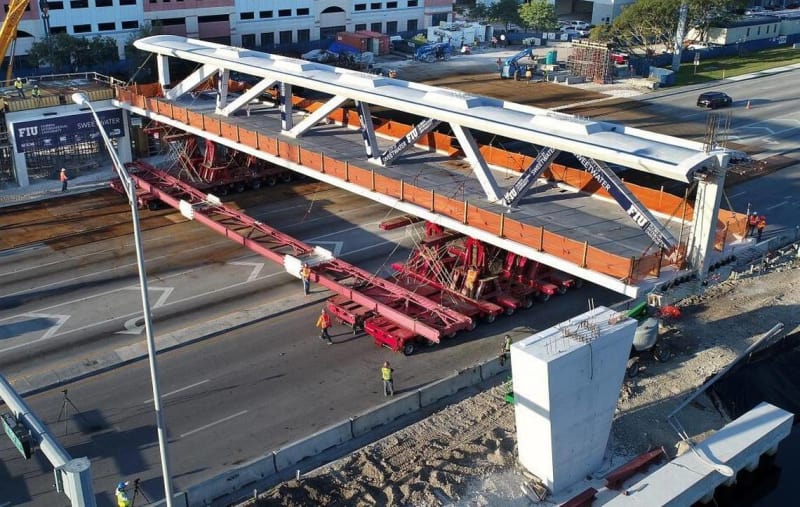
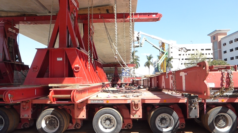
I no longer think a large chunk broke from the deck, but that 11-12 sheared as gwideman shows in IV-23-17:09. Appster has construction photos (IV-23 Mar-22:21) - it appears the deck was poured first (photo 6,7), then members second (photo 8), though can't tell how end/diaphram was done, or where PT rod anchors were set (FIU print only shows top). I think the shear/break point was the deck instead of going into diaphram - there's a 'box extension' on 'back' of #12 (where PVC pipe comes out) with what appears to be a "pour line" - this is where 12 broke/sheared, but the ends of 11 (4' to 6'?) and 12 (2' to 4'?) completely disintegrated.

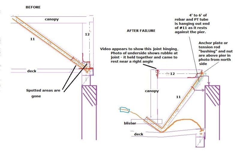
Below is a (very) rough drawing of how I think things ended up (I can only do 90o rotation - using sailee119's for outline).
Bottom of 11 and 12 were shattered (red dots) - while rebar from bottom of 11 was still fairly straight (I don't understand how this could happen). It doesn't seem rotation of the north end, with ends of members sliding across/landing on top of pier, would have enough force to shatter that much rebarred concrete.
FIU_failure_ey7t53.jpg


(Note: I thought this end was similar to the south end 2-3 PT rods, but print shows top of upper rod a dead end anchor (adjusts from below) and lower rod adjustable from top. Anchor plate spec is 8"x12" but 11's upper tube plate in photo resting on top of pier looks smaller (like those I see on PT rod sites for the nut end). Both rods on 11 were adjusted from top, and they appear to have a LOT of threads showing (I don't if this is normal). I tried to find a good photo of 2-3 since it had been adjusted earlier, but couldn't find any with good detail (2-3 blister photos show the top opened up/chisled(?) larger, similar to 10-11)
 
WetlandGeek,

The underside of the deck is taper when it was on the four transporters. In the final position the support is the flat bottom of the downstand beam (or end beam). Alignment should not be a problem for a simply supported condition. I expect the bearing pads to have some compressibility to take out any small unevenness.
Transporter_supports_uhucvr.png

4 Transporters tied together by 2 huge girders supporting the bridge with timber wedges

I do agree with your sentiment that the structure could have suffered some damage in the move. On the transporters it was confined by large timber wedges. Although the transporters were bolted together by two huge girders to form a rigid table but the jacks were not and definitely have some flexibility. Since one end acts as a pivot while the other traveled 1/4 of a circle, any flexibility in the jack supports will cause the 4 supports not moving simultaneously and the bridge will be bent laterally.


I agree the bridge in your link did rock from 0.44 to 0.50. While this does not necessarily translate into damage but it clearly shows the cantilever did experience some disturbing forces. My approach would be include some dynamic load as a load case in the analysis of the maneuver.

When cracks were reported and confirmed not affecting safety at the north side, same side when it rocked, my initial thought was the bridge might have suffered some damages from the dynamic condition.
 
Status
Not open for further replies.
Back
Top