Navigation
Install the app
How to install the app on iOS
Follow along with the video below to see how to install our site as a web app on your home screen.
Note: This feature may not be available in some browsers.
More options
Style variation
-
Congratulations TugboatEng on being selected by the Eng-Tips community for having the most helpful posts in the forums last week. Way to Go!
You are using an out of date browser. It may not display this or other websites correctly.
You should upgrade or use an alternative browser.
You should upgrade or use an alternative browser.
Miami Pedestrian Bridge, Part V 71
- Thread starter dik
- Start date
- Status
- Not open for further replies.
chris snyder,
Good drawings! Seemingly each day we are getting closer to what happen.
As Gwideman has pointed out previously you need to be careful with the information as Appster posted on 23 Mar 18 22:21 is a animation and not the real thing. While it depicts the method well we do not know exactly the details of the pours. If you watch the video the whole bridge was constructed with a single workman seen. Magic?
Re: Clearer view of "puff"
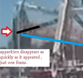
Perhaps the puff is part of the banner zip-tied to member 11. When 12 falls, the puff goes away as banner is pulled down with it. Banner remnants can be seen between deck slab and pylon in NTSB video. Note how the banner shredded on member 3 in clear view on the truck dashcam video.
Perhaps the puff is part of the banner zip-tied to member 11. When 12 falls, the puff goes away as banner is pulled down with it. Banner remnants can be seen between deck slab and pylon in NTSB video. Note how the banner shredded on member 3 in clear view on the truck dashcam video.
Slow motion of the collapse from youtube.
slow motion
As the video starts, note the puff of white dust to the right of the worker on the top of the canopy. The dust than dissipates and then returns, maybe blown away by the wind? The dust would appear to show that the worker was chipping away the concrete at the time of collapse, and not post-tensioning. There is then a puff of black on #12, then a puff of white dust on #12 as the collapse begins.
It appears that the bridge fell during the preparation for post-tensioning so that would indicate that the bridge was already unstable or damaged.
Appster,
Do correct me if I misinterpret your thought of your post on 27 Mar 18 21:21.
I believe the PT strands you mentioned on either side of No.12 should be PT rod. The diagrams of them have been provided by Alfie.Tx on 27 Mar 18 13:49.
The drawings would suggest they are holding down bolts for the designer to fix both spans at the pylon position but allow the two opposite ends to freely slide to mitigate the longitudinal thermal stress.
saikee119 (Structural) said:The underside of the deck is taper when it was on the four transporters. In the final position the support is the flat bottom of the downstand beam (or end beam). Alignment should not be a problem for a simply supported condition. I expect the bearing pads to have some compressibility to take out any small unevenness.
The plans show spreader plates on top of transporter units across both transporters. The transporters are also positioned on the ends of the bridge.
I just saw this on YouTube. He sounds very confident, which is probably a bad thing.
Why the Miami bridge broke - Prof Simon
--
JHG
Why the Miami bridge broke - Prof Simon
--
JHG
Alfie.tx said:The PT tendon that is securely attached to the bottom deck had a snag with the bottom most ties and reinforcement of #11,......
sure seems plausible . At the instant of that frame you posted, the tendon hadn't yet unzippered from #11 . As the deck continued down with #11's bottom hung atop pylon, it ripped the tendon out straightening rebar as seen in NTSB pictures ?
Holding that thought to see if it withstands scrutiny....
Thanks for the feedback ! old jim
Never trust a computer with anything important...
bimr said:The plans show spreader plates on top of transporter units across both transporters. The transporters are also positioned on the ends of the bridge.
I am afraid you are behind with the history. First the north side has a concrete barrier making the original transporter configuration too much work. A change was introduced probably necessitated the PT rods introduced in No. 2 & 11 as No.11 according to the proposed drawing has no PT system. The revised transit support arrangement has two overhanging cantilevers causing No.2 and 11 suddenly taking tension not anticipated in the proposed drawings. The change broke the bridge indirectly!
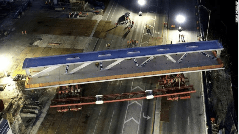
This was how the bridge supported during execution.
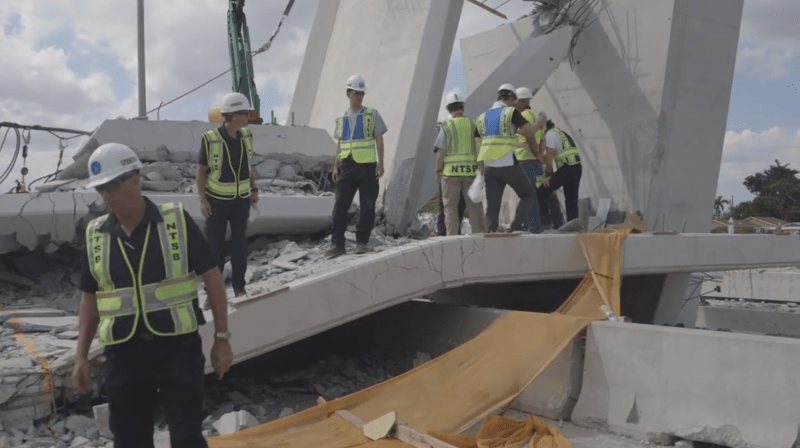
You can see the concrete barrier or divider here. It broke the fell bridge by locally hogging when the bridge failed by sagging. The sagging point is at the lower left corner of the photo.
Hold on a minute here Prof. Simon. :
I calculated the stress in 11 on the pier with its axial load and assuming two PT bars at 250K tension each. Under dead load only the axial stress in 11 with a reaction of 887 kips after removing DL of 12 and half of canopy between 11 and 12 = 1508 k/ 22 X 24 = 2.85 ksi with no PT bars. With the two PT bars at 250k axial stress would be 3.8 ksi. If one was tensioned to 280 kips (maximum at 70%of ult.) then if one was taken to ultimate of 390 or 400 K the average axial stress would be 2178k /22 x 24 = 4.125 ksi average at the moment of ultimate breaking strength. After the break the average stress would be about 3.38 ksi with axial stress of 2.85 ksi plus a moment of 280 x 0.75 (allowing 3" to cL of PT bar = 210 k-'. With S= 22 x 24^2 /6 = 2112 in3 bending stress would be 210 x 12/2112 = 1.19 ksi. After failure of the tendon if it actually did fail the maximum comp. stress in 11 would be 2.85 + 1.19 ksi = 4.04 ksi. this is only slightly above the stress with DL + 2 PT bar stress of 3.8 ksi. Was the shock of the ultimate failure of a PT bar if true enough to fail a borderline structure or was the moment created by one PT bar enough for 11 to fail in bending.
Why would they even consider changing anything if the structure was so borderline. If you keep stretching a PT bar and the load does not increase better stop right away. Looking at the one dash cam video though it does appear that 11 deforms too much at the top and bottom before the failure. Video is of low quality but NTSB could have NASA or someone make the video clearer by computer enhancement.
Sorry Prof Simon but I am still a skeptic who of course does not even know for sure what strength of concrete was used in the web, deck or canopy.
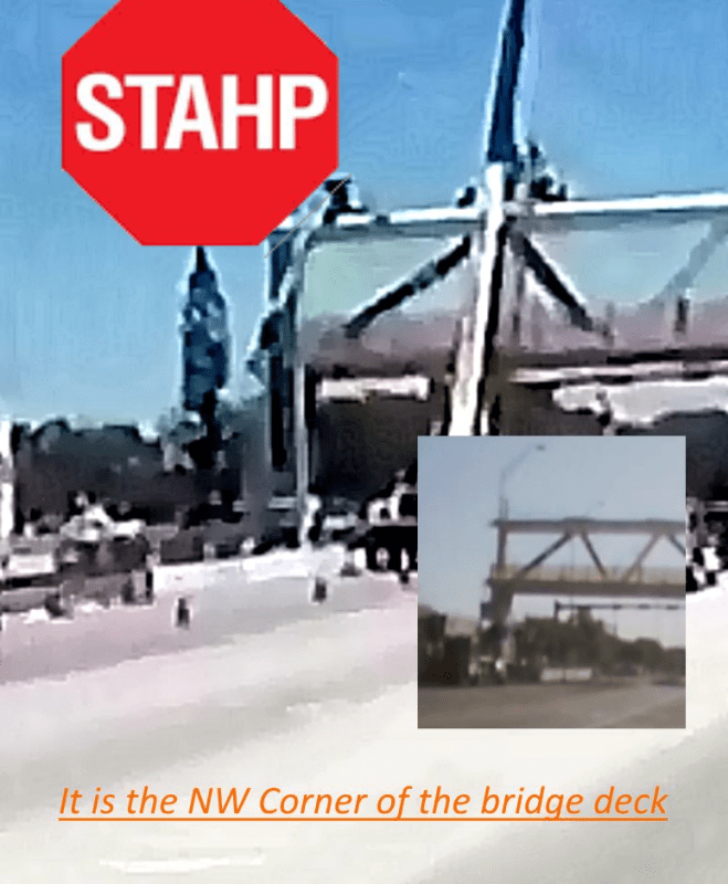
gwideman by post 27 Mar 18 07:53 has already shown the deck could clear off the abutment after dropping about 13'. In view of the interest expressed on the lateral protrusion disappearing during collapse I enclose a couple of graphs showing the movement of the north edge of the deck.
I should say my assumptions differ from gwideman slightly but the overall result is a reasonable match. He assumed the sagging point 36.83' from the north edge while I used 37.13'. I believe he clear the seating width for the full end beam 2'10-1/2" width when the bridge drop 13'. I assume the 175' span between bearings so my deck clearing off distance is half of him and so my drop is only 9' approximately. However my graph does show a 13' drop if the clearing distance is doubled.
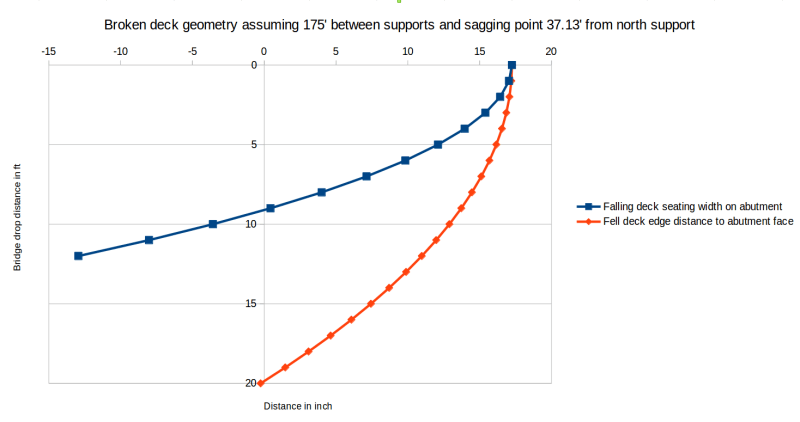
The above graph also depicts how much distance the edge of the fell deck from the face of the abutment. Both gwideman and I assume the ground level is 20' from the top of abutment. When the fell bridge lying flat on the ground my graph shows a clearance of 0.25" distance which is not too far off from the actual structure.
The graphs assume the broken segments can be summed back to the original 175 length but in reality with concrete spalled and structure folded at more than one location the total length of bridge could have changed. Nevertheless the blue graph above would suggest the deck was moving south if something were protruding north during the collapse. Therefore it may be a possible explanation for why the protrusion retracted.
I should say my assumptions differ from gwideman slightly but the overall result is a reasonable match. He assumed the sagging point 36.83' from the north edge while I used 37.13'. I believe he clear the seating width for the full end beam 2'10-1/2" width when the bridge drop 13'. I assume the 175' span between bearings so my deck clearing off distance is half of him and so my drop is only 9' approximately. However my graph does show a 13' drop if the clearing distance is doubled.

The above graph also depicts how much distance the edge of the fell deck from the face of the abutment. Both gwideman and I assume the ground level is 20' from the top of abutment. When the fell bridge lying flat on the ground my graph shows a clearance of 0.25" distance which is not too far off from the actual structure.
The graphs assume the broken segments can be summed back to the original 175 length but in reality with concrete spalled and structure folded at more than one location the total length of bridge could have changed. Nevertheless the blue graph above would suggest the deck was moving south if something were protruding north during the collapse. Therefore it may be a possible explanation for why the protrusion retracted.
As to software that designs connections, what exists is only capable of designing standard, repetitive-type connections. The FIU bridge would not qualify and the connection details would first need to be drawn, preferably by hand, and then potential failure planes contemplated so that supporting calculations can be made that indicate adequate reinforcement is in place to prevent failure.
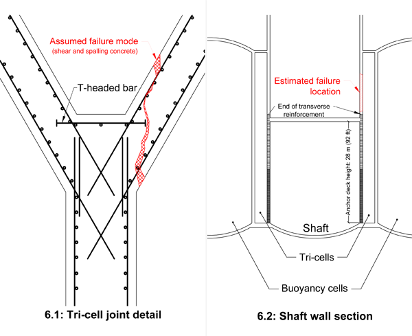
A famous example of what happens when this is not done is the $180Million Sleipner A-1 North Sea concrete oil platform that sank in the Gandsfjord outside of Stavanger, Norway in 1991 when it was undergoing ballasting in preparation for the addition of its drilling rig. It failed in shear as a result of poor geometry and inadequate reinforcement. The failure is shown below. If that T-headed bar had extended out to the far surface it might not have failed.
A famous example of what happens when this is not done is the $180Million Sleipner A-1 North Sea concrete oil platform that sank in the Gandsfjord outside of Stavanger, Norway in 1991 when it was undergoing ballasting in preparation for the addition of its drilling rig. It failed in shear as a result of poor geometry and inadequate reinforcement. The failure is shown below. If that T-headed bar had extended out to the far surface it might not have failed.

saikee119 Re strand vs PT rods
No I was referring to the strands immediately either side of 12 in the deck, not in member 12 itself. The concept drawing section of the bridge shows 6 x 19 strands either side of 12 and smaller or fewer strands outboard. The smaller bundles seem to be inboard and would cary less tension in the most critical area. The post you refer to showed bar in member 11 and in bottom of 12.
On another subject
Does anyone here have any evidence besides the professors video to verify that they were actually attempting to add tension to the PT bars to close a crack. If true no experienced crew would keep jacking on a PT rod if the tension is not increasing; either the bar is into the yield zone, anchorage has failed or something else is not right. From 70% if that is what it was at to failure would involve more than a bit of elongation. Did they or did they not know the stress history of these PT bars.
And another. Does anyone have any idea what PT strands were planned for the canopy and when these were to be tensioned before moving the bridge.
racookpe1978
Nuclear
Pontduvin
Good dwg of the concrete "Y" failure. Please look at the Columbia bridge failure thread: There, another "diamond" diaphragm separated very nearly identical to the oil platform failure you show.
Good dwg of the concrete "Y" failure. Please look at the Columbia bridge failure thread: There, another "diamond" diaphragm separated very nearly identical to the oil platform failure you show.
- Moderator
- #115
Appster
The crews have to increase the tension in order to back off the nut to relieve the tension.
The failure appears to be shear or crushing of member 11.
The PT rods do not appear to be broken.
The crew had the jack on the lower rod of member 11. In some of the pictures he lower end of the rod appears to be anchored into the deck. Had the rod broken it is doubtful that it would have zippered out of member 11 as much as it did.
Bill
--------------------
"Why not the best?"
Jimmy Carter
racookpe1978
Nuclear
A different thought: Look closely at the rebar as it protrudes from the broken concrete.
It's pristine, clean, clear of ANY concrete blocks or remnants or pieces. Only a light coating of dust. As if the rebar were "oiled" or painted/didn't adhere to the concrete around it.
With the 4 inch dia plastic drain pipes at each connection, would that not also contribute towards a weak jint at each connection?
-
1
- #118
-
2
- #119
This is Tomfh's animated GIF from 18 Mar 18 02:49 (Part I), but I've sped it up and looped it.
The faster frame rate and looping allows us to make better use of our visual system to see continuity of action.
(All are cautioned that this is still just 7 frames of fuzzy zoomed dashcam video, albeit with Tomfh's "dolly zoom" enhancement).
Half-size version below, full size version is in the attachments. (A bit overpowering to post in line, I thought.)
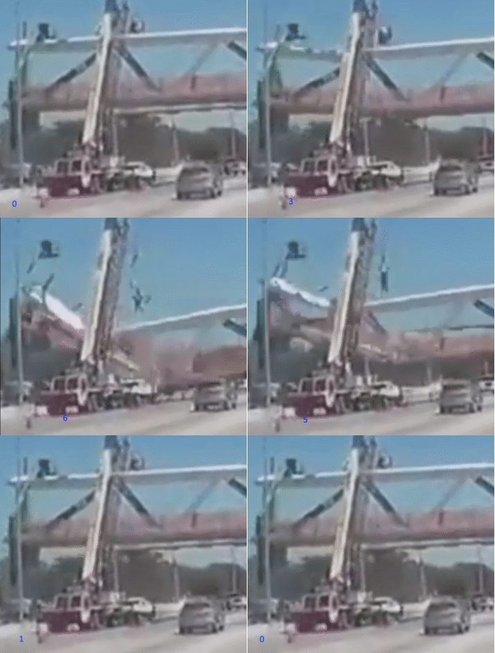
[Edit: I decided to post slightly slower version: 160ms per step. If dashcam was 60 frames per sec, then this is slowed by a factor of 10]
The faster frame rate and looping allows us to make better use of our visual system to see continuity of action.
(All are cautioned that this is still just 7 frames of fuzzy zoomed dashcam video, albeit with Tomfh's "dolly zoom" enhancement).
Half-size version below, full size version is in the attachments. (A bit overpowering to post in line, I thought.)

[Edit: I decided to post slightly slower version: 160ms per step. If dashcam was 60 frames per sec, then this is slowed by a factor of 10]
Appster,
Is this what you are looking for the strand arrangement for the canopy and deck?
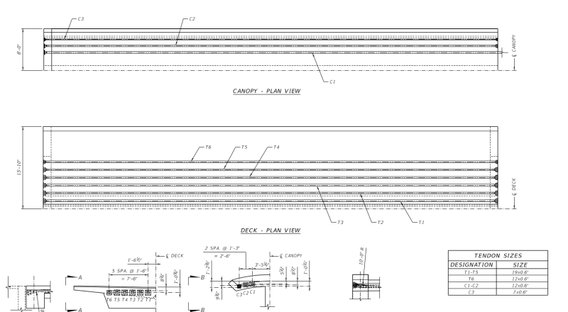
It is page 112 of the 173-page MCM_FIGG proposal. The web page has been cited several times in this site. Think EingineerEIT first gave the web address on 16 Mar 18 15:04 in Thread 1. I believe it in in FIU site too.
Is this what you are looking for the strand arrangement for the canopy and deck?

It is page 112 of the 173-page MCM_FIGG proposal. The web page has been cited several times in this site. Think EingineerEIT first gave the web address on 16 Mar 18 15:04 in Thread 1. I believe it in in FIU site too.
- Status
- Not open for further replies.
Similar threads
- Question
- Replies
- 27
- Views
- 28K
- Replies
- 0
- Views
- 1K
- Replies
- 2
- Views
- 7K
- Replies
- 13
- Views
- 13K
- Replies
- 6
- Views
- 3K

