Continue to Site

Eng-Tips is the largest engineering community on the Internet

Intelligent Work Forums for Engineering Professionals

  • Congratulations KootK on being selected by the Eng-Tips community for having the most helpful posts in the forums last week. Way to Go!

Miami Pedestrian Bridge, Part VIII 80

Status
Not open for further replies.

JAE

Structural
Jun 27, 2000
15,444
A continuation of our discussion of this failure. Best to read the other threads first to avoid rehashing things already discussed.

Part I
thread815-436595

Part II
thread815-436699

Part III
thread815-436802

Part IV
thread815-436924

Part V
thread815-437029

Part VI
thread815-438451

Part VII
thread815-438966


Check out Eng-Tips Forum's Policies here:
faq731-376
 
Replies continue below

Recommended for you

hokie66, I'd agree with you that the article seems to be well written for its intended audience.


Check out Eng-Tips Forum's Policies here:
faq731-376
 
Miami-Herald said:
FIU had launched and heavily promoted a center for ABC at its engineering school, and explicitly saw use of the technique for its pedestrian bridge as a demonstration of its efficiency.

Such quick-bridge construction effectively ruled out a true cable-stayed bridge. Cable-supported bridges are built in sections and in place, which requires extended road closures. Truss designs, in contrast, are ideal for the accelerated approach, engineers say.

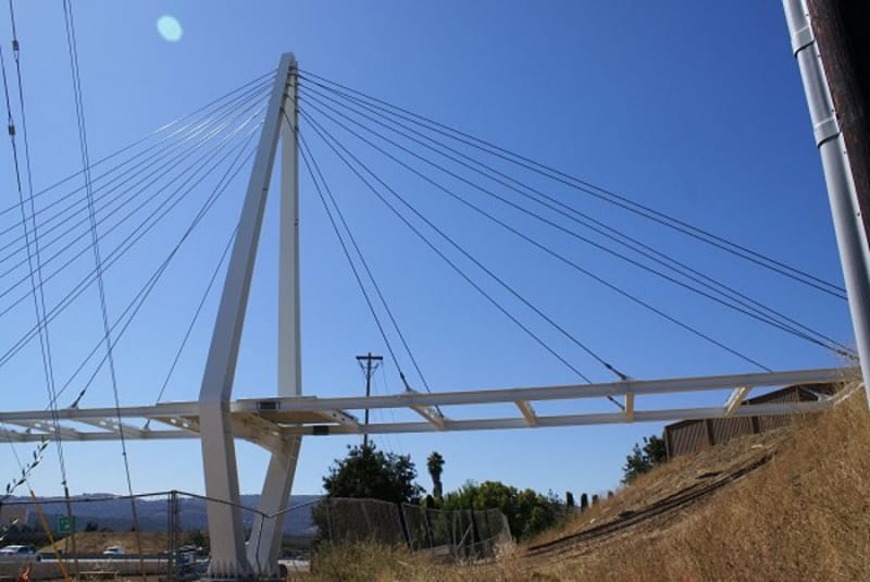
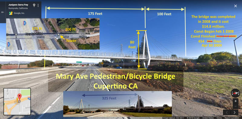
I posted this bridge in Part IV but I'm re-posting it because it demonstrates that the above premise is not valid.
Time Lapse Video: Link

Mary_Ave._tnrl44.jpg


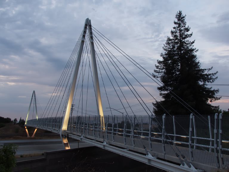
The Mary Ave. (Don Burnett Bicycle-Pedestrian Bridge) is built to withstand SF Bay Area earthquakes. As the photo demonstrates they could have built HALF of this bridge and probably have had plenty of money to dress it up & make it the deck wider, while still employing a method of ABC. This bridge would have needed support briefly. The extra unused lane on the Tamiami Trail/Hwy 41 would have served nicely.
dsc09014_qdyeir.jpg


9360717491_e2e538ee3b_b_jcw17o.jpg
 
Yes, there are plenty of cable stayed pedestrian bridges built while the roadway below is in use.

And the bridge in Cupertino CA is structurally honest, and IMHO better looking than the Miami bridge was going to be.
 
I wonder about the difficulties of anchorage to support the asymmetrical weight of a pure cable-stayed bridge and the concentration of the weight on the one central pier that would happen, given the close proximity to the canal. It's also about 12 feet wide, or about 1/3 the width of the FIU bridge and likely a lot more elastic/jouncing making for a less desirable hangout spot.
 
thebard3 said:
...but that 'undernourished' strut....
I'm thinking that is a case of an overly active use of a thesaurus. (Maybe a change from underweight to undernourished?)
 
I was quite happy to have another structural term in my vocabulary. The bridge was demonstrably understrength, and strength often relates to nourishment, so I give the journalist a bit of leeway.
 
I quite like that description. Not enought "meat on the bones" if you like I think gets the message over very well.

I thought that was a very well written article.

Remember - More details = better answers
Also: If you get a response it's polite to respond to it.
 
I'm feeling confident so here's my two sense on the failure progression:

a) The base of #11 fails early - essentially a column with a wedge shaped base that slips and crushes against #12. This failure is not explosive, rather it is progressive as PT is ratcheted up.
b) The displacement and crushing of the lower end of #11 results in the upper canopy being pinched downwards at the #10/#11 bubble.
c) Further PT on #11 also loads energy into #10 which bows upwards while #11 bows downwards.
d) This deformed system continues to be loaded with PT plus gravity until the upper end of #11 blows apart. This is when we first see the obvious disaster unfold.
e) As #10 is restored, the north end of the #10/#11 bubble is punched out of the failed canopy creating an illusion of time lag in the canopy collapse north/south of the bubble.
f) The lower deck fails across the #9/#10 joint.
g) The north end of the bridge is dragged down, tearing the PT cables out of #11.

Unfortunately, this disaster truly was amateur hour.

My sincerest condolences to the victims and their families.

 
I'm with you up to d)

Looking at this extensively I think it's the base of no 11/12 which fails first or maybe at the same time as the top. This action is enough to push no 12 off the plinth. If you look closely at the top of 12 during the many slo mo videos, the canopy at the 12 end falls at the same time as the rest for about half its height before the canopy collapse drags it back over the plinth into its final resting position.

One of the survivors quotes a sudden loud noise just before the collapse. Could be either end of 11 IMHO

Remember - More details = better answers
Also: If you get a response it's polite to respond to it.
 
OK - I understand what everyone has explained. And I am not a structural engineer, but I have to ask, what if the joint between diagonal #11 and the deck had not been a "cold joint" but a continuously poured section of concrete (not that that would even have been possible). I might have thought that critical "joints" would have been spec'ed to be completed in a single pour for this reason.
It looks a little to me as if the designer was used to building steel bridges where a properly done weld would be stronger than the base metal. It looks as if concrete bridges may be a different matter.
What does anyone think?
 
Hello Again,
I have been working (slowly) on a frame by frame of the original dashcam images.
It is easy to draw boxes aligned with the image shapes, the hard part is to align the images frame to frame because of the movement of the truck. It is very clear that the canopy drops at the #10-11 blister before any other movement can be detected at the resolution of the dash cam. #12 appears the remain vertical at this moment. To me this implies a break at the top of #12 and requires #11 to get shorter. There is also an increase in the angle between #10 and 11, so something had to give there.
I'm working in powerpoint 'cause that's what I'm familiar with, but haven't found a way to capture the slideshow. I'll post as soon as I can convert to a reasonable format.
Thank you,

SF Charlie
Eng-Tips.com Forum Policies
 
SFcharlie - Hence why I think the base of 12 and 11 was initially pushed out just beyond the support (would in essence make no. 11 "shorter").

tomcat - I think many are agreed that the design of the bridge was not standard and that the analysis of the joints and connections between the different elements was a lot more complex than may have been imagined / undertaken. It has also been noted many times that the number of concrete truss like designs is very limited - probably for good reasons.

However we don't have the inside knowledge on the level of analysis and design scrutiny / review which was undertaken.

Remember - More details = better answers
Also: If you get a response it's polite to respond to it.
 
LittleInch (Petroleum) said:
I think the base of 12 and 11 was initially pushed out just beyond the support
I can see the upper part of #12, and it doesn't move. I suspect that the little ~3 inch high bit of concrete between #12 and 11 failed. What happens at the top is confusing since in the aftermath, we see the blister more or less intact, but separated from the canopy, but somehow 11 became hinged re #10. Also in the aftermath, 11 is damaged at both ends. I wish NTSB would release the photos of the elements as they observed during the deconstruction of the north end.
Respectfully,

SF Charlie
Eng-Tips.com Forum Policies
 
IRstuff (Aerospace) said:
possible to screen capture the slide show into a video
Thanks!
Yes, I'm sure you're correct. I had hoped that Microsoft would provide a way to export the show as a gif or video file, but I haven't found the correct pulldown. I'll google it.


SF Charlie
Eng-Tips.com Forum Policies
 
Status
Not open for further replies.

Part and Inventory Search

Sponsor