Continue to Site

Eng-Tips is the largest engineering community on the Internet

Intelligent Work Forums for Engineering Professionals

  • Congratulations KootK on being selected by the Eng-Tips community for having the most helpful posts in the forums last week. Way to Go!

Miami Pedestrian Bridge, Part X 50

Status
Not open for further replies.

JAE

Structural
Jun 27, 2000
15,444
A continuation of our discussion of this failure. Best to read the other threads first to avoid rehashing things already discussed.

Part I
thread815-436595

Part II
thread815-436699

Part III
thread815-436802

Part IV
thread815-436924

Part V
thread815-437029

Part VI
thread815-438451

Part VII
thread815-438966

Part VIII
thread815-440072

Part IX
thread815-451175


Check out Eng-Tips Forum's Policies here:
faq731-376
 
Replies continue below

Recommended for you

MikeW7 Good point, I was not sure I wanted to encourage not paying. I use Tor session in Brave browser. But NYTimes is wise to this too. Speaking of NYTimes.com, check out the nice ped bridge in that Hong Kong protest article. Slightly relevant here because they loaded bridge.

Loaded walkway - New York Times owns this photo:
merlin_156531063_f03d5352-490a-41dc-a3d7-cf287271c3d0-superJumbo_hzqin2.jpg
 
jrs_87 - I don't read NYT or WaPo as a habit, but I get sent there often by Reddit and it ticks me off when I realize what happened. It like being Rickrolled without the fun dance music.
 
MikeW7 LOL I'm the only person that in the 80's focused on the fine brick construction in this music video. Check out the structural arches and curves featured throughout. Now I just Rickrolled you.
 
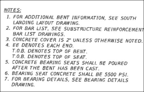
From Notes on Drawing B-73, we see what i have said many times -"CAD drafting lets you make mistakes at the speed of light".
Check Note 4 - obviously a copy/paste move.
FIU_Notrs_B-73_ozadhr.jpg

I am not so sure that that point alone added to the potential for collapse, however.
 
I went back to have a second look at the Barnhart Movement Plan and ended up a bit disoriented. See the pictures below (page numbers are pages within the 11-page PDF). They have been cropped and scaled so they are about the same size. Am I being too picky about all the inconsistancies and mis-labeling? If I were grading this there would be a lot of red ink....

Page 11 (below)
[ul]
[li]Pier end is to the right in this drawing, which is reversed compared to other 4 drawings.[/li]
[li]SPMTs are in correct place with respect to bridge orientation, but look wrong compared to drawing on Pages 5, 9 and 10 because bridge is reversed.[/li]
[li]Critical points are labeled 1 to 5, going from Pylon to Pier. In page 5 drawing the numbering is reversed.[/li]
[li]Pylon end is slightly higher than Pier (correct slope)[/li]
[/ul]
Page_11_-_deflection_and_rotation_r2vhdj.jpg


Page 3 (below)
[ul]
[li]No end or column labels (cover page, not a big deal)[/li]
[li]Compared with Page 11, the SPMTs are located in the same place with respect to the side margins of the drawing, but in this drawing the bridge is reversed left to right which puts the SPMTs in the wrong location relative to the bridge columns. Compare with next 3 drawings which have same bridge orientation as this drawing, but the SPMTs properly located.[/li]
[li]Pier end is high (wrong slope)[/li]
[/ul]
Page_3_-_cover_xgwmiy.jpg


Page 5 (below)
[ul]
[li]Not shown in this cropped image, but N-S are marked.[/li]
[li]Critical points are labeled DISP1 to DISP5, going from Pier to Pylon (opposite of Page 11 labeling)[/li]
[li]Pylon end is high (correct slope)[/li]
[/ul]
Page_5_-_sensors_pjgtyg.jpg


Page 9 (below)
[ul]
[li]Deck is level[/li]
[/ul]
Page_9_-_Lateral_bracing_lq0fea.jpg


Page 10 (below)
[ul]
[li]Deck is level[/li]
[/ul]
Page_10_-_Strain_Gauge_locations_k9pg97.jpg
 
Re Moving bridge, which way is north
Mike - just checked something - am I wrong?
the 1% slope is 1.74 feet for the main span.
The max allowed angle change during moving was 0.5 degrees ???
My old HP11C says the tangent of 0.5 degrees is 0.0087 or less than 1%. So they had to exceed the spec limit for moving it just to lift it on the supports?
Probably not the worst thing that happened to it.

 
Vance Viley said:
moving limit

The 0.5 degree limit refers to relative twist (torsion) perpendicular to deck at the lift points. Calculations on this limit in part depend on the distance between the lift points longitudinal to span. Tilt instruments were glued to the span above the the lifters.

 
MikeW7 said:
I mosied around the Pate-signed construction plans last night and this is what I found:
Although these are signed plans, there is a more recent, different set which doesn't seem to be available. These plans don't show the bridge in its final location, shifted 11 feet to the north, so that the pylon pier is on fill next to the canal. Page 18 of the OSHA report shows the true location of the bridge, which is different from Sheet B-4 in the signed plans.

Has anyone seen the revised, really final construction plans?
 
jrs_87 said:
Franklin Hines PE FIGG (Was at bridge move), 2007 CNN Interview

According to his LINKEDIN Hines was a first responder to the I35W collapse, and was part of the FIGG team that was selected to rebuild it:
[ul]
[li]Crosstown Connector Reconstruction, Minneapolis, Minnesota (2007-2009)[/li]
[li]IH35 Bridge Collapse Incident Response-First Responder, Minneapolis, Minnesota (2007-08-01)[/li]
[/ul]

As you've found out, the contrast between the pre- and post-collapse impressions of FIGG Bridge, Linda Figg and Denney Pate is stunning. FIGG, Figg and Pate were engineering rock gods before they got involved with FIU and MCM, and now their reputations are in tatters. My impression is that this was a minor project in their world view, and senior management and engineering probably knew very little about it until the initial cracks were discovered in February. Given Linda Figg's penchant for beautiful design, I'm surprised she even OKed the design, or showed up for the bridge setting ceremony, because this had to be one of FIGG's least attractive projects - it was an outlier in size and aesthetics. As I alluded to in an earlier (now deleted) post, following the money trail is going to be interesting....
 
Vance Wiley said:
Re Moving bridge, which way is north
Seems like the docs (and myself) refer to the pylon end as the "North" end since that was it's intended final orientation.

Vance Wiley said:
the 1% slope is 1.74 feet for the main span.
The max allowed angle change during moving was 0.5 degrees ???

I went back through the SW view videos at the construction area (Move part 1) and prior to final setting (Move part 3) and it is hard to tell if or when they adjust tilt. Prior to seating the bridge there are many adjustments for side-to-side and end-to-end tilt, but it is unclear if this is anything more than just raising the overall height in discrete steps.

I then went back to the original version of "Move Part 3" - after it was cropped but before it was slowed down [uploaded to Whirled Gnus as Move part 3 - SW view (fast)] - and the SPTM sequence (after the bridge is squared up N-S) appears to be:
[ol 1]
[li]lower north end slightly[/li]
[li]raise south end a lot[/li]
[li]raise entire span and move into final position[/li]
[li]lower south end (slightly) to final seated position[/li]
[li]lower north end (slightly) to final seated position[/li]
[li]drop the towers and scurry back to the parking area[/li]
[/ol]

This is confusing as hell because 1. and 2. imply that either:
[ol A]
[li]The pier end was installed higher that the north pylon end, contrary to the PGL elevations in the construction plans: Pier 30.693 and Pylon 32.44 (or my misunderstanding of what these numbers represent).[/li]
[li]The bridge was constructed with the Pylon end significantly higher than the pier end.[/li]
[li]The span was heavily tipped during the move as the pylon end was driven over the highway median strip.[/li]
[li]I'm not seeing something.[/li]
[/ol]

My impressions:
[ol A]
[li]Impossible ?[/li]
[li]No logical reason to do this ?[/li]
[li]A possibility because the initial setpoints/calibration levels were lost during the mysterious computer shutdown during the move.[/li]
[li]A possibility because the videos are not super high-resolution, the SW viewpoint is elevated and off to the side, and 1% tilt is not much.[/li]
[/ol]

FIU was also bragging about this being the largest pedestrian bridge moved by SPTM in U.S. History. That's quite a feat by itself, but then they had to increase the degree of difficulty by making a sharp 90 degree turn while also running off a curb and over a median.

More wierd stuff to add to the ever-growing pile of wierdness.
 
Wetlander (Specifier/Regulator) - This link has the Release For Construction Plans and Addenda. Link
It can be found in the FIU list of documents: Link

 
SFCharlie - I was just repeating what I remembered (vaguely) about something I read...

In the section titled A Record-Breaking Move:
According to FIU this was “the largest pedestrian bridge move via a Self-Propelled Modular Transportation (SPMT) in U.S. history.”​

I missed the clarifier about "bridge" and "U.S. history"
Parent post has been edited for clarity. THX for the reminder to always provide sources...

 
MikeW7 said:
The bridge was constructed with the Pylon end significantly higher than the pier end.
or:
The soil under the construction site that the SPMTs started on wasn't level
The street wasn't level.
The SPMTs weren't centered on the crown of the street
Only Denney Pate's phone knows

SF Charlie
Eng-Tips.com Forum Policies
 
SFCharlie - Whatever the reason, there was a whole lotta jackin' going on right before the SPMTs moved east the last few feet. I'm guessing significantly more than the 0.5 degree allowance.

If the monitoring equipment and SPMT move-meister were doing their jobs, shouldn't the bridge have been nearly level during the entire move? The purpose of the rotation sensors was to provide real-time feedback during the move, as well as provide a permanent record.

The Move 2 - ground level video (at 1:24) shows a guy wearing what appears to be an RC-type controller at waist level. Could he be the move-meister?
 
MikeW7 said:
I was just repeating what I remembered (vaguely) about something I read...
My memory has been pretty vague too.
I'm sorry, I realized, I've been kind of cynical this morning...
Yes, I went back and watched the videos again and something definitely goes wrong with the north SPMTs as they go over the median. They are supposed to stay level as a unit of two. The whole arrangement starts to tilt. they back up, adjust tilt and go forward again. The Remote operator comes over to the north end to watch. Maybe this is the wifi failure that was mentioned.

SF Charlie
Eng-Tips.com Forum Policies
 
SFCharlie said:
Maybe this is the wifi failure that was mentioned.

And they also had a mysterious data glitch that lost their setpoints/calibration during a "break" when the computer was turned OFF and ON.

ADD: Could the WiFi blackout have occured because the operator moved from behind the movers (where both SPMT groups were in his line-of-sight) to a position under the pylon end, just before the SPMTs started over the median? Instead of "operator error" you'd have "poor Wi-Fi reception" as an excuse....


This structure was designed to endure whole-body force loading like large crowds, heavy rain, and hurricane winds, not localized lifting/shifting/twisting in the constrained areas where the canopy was chained to the SPMT arms. The bridge was rigid-like in large-scale 2D, but fragile when localized torque and flexing was applied. I fired up a couple of old engineering school neurons on those sentences - did they make any sense?
 
"What if some of the Sag in the bridge during transport remained as camber, until Truss No. 2 & Truss No. 11 are detensioned?"
I don't think anyone weighed in on this point, so I will provide my thoughts.
IF the members 2 and 11 were tensioned while in the forms they likely caused upward movement of the end bays because of the compression added in the members. Then lifting under nodes 3/4 and 9/10 could result in those nodes being lower (elevation wise) than the ends by some small amount.
When set on the pier and pylon and with the PT remaining in 2 and 11, removing the supports from the transporters leaves a longer span than as transported, no cantilevers which added lift to the shorter center section,and the structure likely settled some more.
Then releasing the PT in 2 and 11 would, theoretically, allow a relaxation of some compression in those members and possibly some lift to nodes 3/4 and 9/10.
Do we have a survey line shot down the length when concrete cured, when the deck and canopy were tensioned, when support conditions changed, when 2 and 11 were tensioned, when on transporters, when transporters removed, and when de-tensioned? Oh, how much that would tell us.
Releasing prestress (bonded or post tensioned) into a tee shaped member with large flange areas will/can cause that member to rise in the center. Is there a calculation presenting the final camber in this structure?
The last stage post tensioning of the canopy across the complete 290 foot structure would add compression to the canopy causing some downward movement of the main span. That will be offset somewhat by the negative moment induced over the pylon, but the expected result is only known after some amount of calculating (of a survey is made).
Hopefully other minds will join in and add other views, and perhaps someone will even find something I have said that they can agree with. Corrections are welcome - the last thing needed is bad ideas.

 
MikeW7 said:
This structure was designed to endure whole-body force loading like large crowds, heavy rain, and hurricane winds
When I went to collage, a long long time ago..., they had a continuous film clip of the Tacoma Narrows Bridge twisting in the wind. (now it's a video loop) Hurricane winds swirl and vary from ground level up, and the canopy is an airfoil. People watching a race would run from one side to the other. They "should" have evaluated torsion.

SF Charlie
Eng-Tips.com Forum Policies
 
Status
Not open for further replies.

Part and Inventory Search

Sponsor