Continue to Site

Eng-Tips is the largest engineering community on the Internet

Intelligent Work Forums for Engineering Professionals

  • Congratulations KootK on being selected by the Eng-Tips community for having the most helpful posts in the forums last week. Way to Go!

Miami Pedestrian Bridge, Part XII 34

Status
Not open for further replies.

zeusfaber

Military
May 26, 2003
2,466
A continuation of our discussion of this failure. Best to read the other threads first to avoid rehashing things already discussed.

Part I
thread815-436595: Miami Pedestrian Bridge, Part I

Part II
thread815-436699: Miami Pedestrian Bridge, Part II

Part III
thread815-436802: Miami Pedestrian Bridge, Part III

Part IV
thread815-436924: Miami Pedestrian Bridge, Part IV

Part V
thread815-437029: Miami Pedestrian Bridge, Part V

Part VI
thread815-438451: Miami Pedestrian Bridge, Part VI

Part VII
thread815-438966: Miami Pedestrian Bridge, Part VII

Part VIII
thread815-440072: Miami Pedestrian Bridge, Part VIII

Part IX
thread815-451175: Miami Pedestrian Bridge, Part IX

Part X
thread815-454618: Miami Pedestrian Bridge, Part X

Part XI
thread815-454998: Miami Pedestrian Bridge, Part XI

Check out Eng-Tips Forum's Policies here:
FAQ731-376: Eng-Tips.com Forum Policies
 
Replies continue below

Recommended for you

RAB678 (Mechanical) 13 Jul 19 19:20 said:
...Bridge photogrammetry 17 by Zac Doyle also on youtube. On my monitor, I can see the end of the crane, vibrate what looks like twice.
:
Also notice a black lifting strap? suddenly shoot upwards out of the picture.

[ol 1]
[li]When you talk about a URL or video, attach a link so we can read/see exactly what you are talking about.[/li]
[li]If you look at the Collapse - N View video you will see that the crane cables are slack and not carrying any weight, right up to the collapse at the end of the video.[/li]
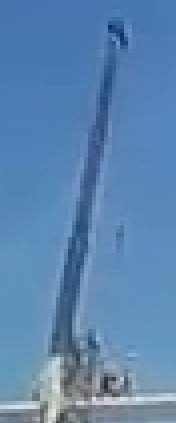
[li]The Zac Doyle video is a heavily processed and interpolated version of the original 1280x720 dash cam video. Whenever there is motion, such as approaching the bridge as shown in the dash cam video, a thin object such as the crane mast will seem to shimmer, shake, etc. because the interpolation area of interest (a small group of pixels) is shifting one row/column of pixels in the direction of motion. As an example of what you were actually looking at, here is a cropped area of the crane mast from dash-cam video Frame 75:
Crane_mast_-_WSVN_Frame075_pveyzv.jpg
[/li]
[li]Also note that the tip of the crane mast has a small eastward extension (see the N- view video) and the dash-cam truck is approaching from a direction where this extension is just coming into view from behind the mast, so there are only a few pixels visible to begin with, and one or two more pixels become visible in each new frame.[/li]
[li]The lifting strap, as you call it, is visible in all frames (see the N-view video), but since it is so thin (only one pixel wide) it may seem to lighten in color (disappear) as it moves from one column of pixels to the next as the dash-cam truck moves closer. See Frame 75 (above) as an example - in some places there doesn't appear to be any cable at all, but if you look closer some pixels in the column containing the cable are a slightly different color than the background.[/li]
[li]For these and other reasons, the way we usually examine videos here is frame-by-frame using the original source. I "enlarge" the frames using an algorithm that replaces each original pixel with a 4x4 block of identical pixels, because just about any other enlargement method will introduce significant interpolation artifacts (stuff that really isn't there). We may have disagreements over what a group of pixels actually represent, but at least we are confident we are all look at exactly the same thing, but just have different interpretations.[/li]
[li]The Doyle video and others are heavily processed, usually with an intent to "enhance" something the author imagines is there. Something similar is done here, on occasion, but the author can explain exactly what was done and why, so everyone else understands the motive and the result, and so they can ask informed questions.[/li]
[li]Don't rely solely on one video when there are more available. Most of your questions are answered (and claims dismissed) by simply looking at the N-View video, for example. The bridge installation and collapse was monitored continuously by at least 3 time-lapse cameras. These are labeled N-view, SW-view and SE-view in my PlayList of Bridge Timelapses videos. Other viewpoints also exist for parts of the move - see my Dropbox Playlist. [/li]
[/ol]
 
RAB678 said:
IF you were lifting the canopy to reverse the sagging and close the cracks.
You would be lessening the friction of 11 base area. Meanwhile.... tensioning the bars. NOW the rods would be under apparently MAXIMUM tension. Basically cocking a gun. Then SNAPPED 11b. The force unloaded would decimate the end. The crane becomes more loaded, cable lift device lets go. Crane vibrates. 11 sends the end outward in pieces. Falls down. Simple conclusion really.

Any thoughts on all this?

The rod did not snap. They were in tact after the collapse. The rods are also checked with predicted elongation with actual load and elongation (standard practice for PT).

Tightening the #11 bottom rod was the final blow but the stresses and cracks were unacceptable before that point.

Tightening the rods would have never fixed the cracks. It added a little bit of shear friction capacity but also substantially increased the horizontal shear stress at the joint. The overall effect was to make the whole situation worse.
 
SFCharlie said:
His web presence has included several channel names. One of his websites was for wedding photography.
He is very enterprising, searching out info on the collapse, including feedback from his subscribers, monitoring this site... He refuses to provides links to his sources. That's how I found this site, search for a link to one of the photos he used in a clip. He has long held that the collapse started somewhere else than 11.12. He holds the participants on this forum in disdain.

Yes, he and some his followers appear to have a real disdain for structural engineers yet they really don't appear to understand the failure, statics, vectors, physics, terminology etc. He has been resourceful for tracking down information but his interpretation is a long stream of nonsensical and illogical gibberish. He tries to act like an expert but clearly doesn't understand fundamentals like equilibrium, FBDs, weight vs mass etc. He is clearly not a numbers person either. That would be critical for an engineer.

In any case, he is just a conspiracy theorist with a stack of information, and severe lack of comprehension. He would do well to at least try to understand the bare minimum fundamentals but it sounds like he never studied any kind of physics so that would be hard for him to do.
 
RAB678 (Mechanical) 13 Jul 19 19:20 said:
If you were lifting the canopy ...
[ul]
[li]If you were lifting the canopy, you'd be using a BIG-ASS crane (500T minimum by my uneducated guess) - pictures on the internet would indicate something about the size as a semi-trailer with 12 wheels.[/li]
[li]You would not be doing it with the boom extended all the way out to infinity.[/li]
[li]And you sure as heck wouldn't be doing it with humans on top of the lift.[/li]
[/ul]
 
I did not mean to steal your idea of the jbar. I've read so much I can't remember everything, sorry bout that. Shout out to Vance one of your longer posts was exactly spot one. I trust you and your thoughts.

Thanks for the video and feedback. I agree crane not lifting bridge.
Although video does seem to have some frames missing.
Are we in agreement that what they did made it fall?
ALTHOUGH NOT their fault but the design side.
May I present to you some thoughts?
Here's something I see.
While on scaffolding all is good. Supports one end to other. Balance. Yea....
Set it on piers.
Now its a Warren bridge truss I-beam. Concrete style.

We all know if the base of 11 or 2 fails its over.
Geometry is paramount.

So....Canopy is in compression, being concrete always expanding and contracting.
But the compression factor makes it always be shorter.
Deck would be opposite. Always elongating. Due to temperature curing.......same reasons.
ADD: No roller to allow for expansion / contraction and the rigidity of the end columns to deck also help prevent the deck from expanding as needed. If it can't expand it WILL sag.
(if you use a simple 4 beam Warren truss, you can see this)

The lack of HANGERS (whatever... a consistent vertical separation type device) on north side allows the parallels of canopy to deck to alter.

Because there are no vertical columns/hangers/risers to stop this.
11 to 10/9 base elongates. 10/9 to 8 base elongates. Sag develops in the deck.
Seeing how concrete does not do well in tension. We hope the rebar will stop it from elongating. Yea...

The canopy is sagging. MORE weight is on 12 and 1. Specifically 12.
12 should not be holding up the bridge. 11 and 2 that's their job.
This weight WILL force the rigid canopy to be preloaded and absolutely snap and project itself downward.
The deck isnt exactly a decent truss with 2/3 down bars. Basically a long wide sidewalk.
Deck cannot ever support itself and is HUNG from the canopy. Which is another issue in itself.....

Geometry is changing. The height to depth ratio isn't great and getting worse.
(for a 950 ton bridge probably quite questionable.)
The forces on 11 and 2 increasing.

1 and 12 were never meant to support this bridge. For additional (flop over to the side) (which is ANOTHER issue in itself) stability only.

All of the cracks seen in pics would be noted.

Oh the rebar in 11 keeps it from buckling down and maybe some friction. But if they would have beefed up 11 as in 2 and added some significant support for the base then maybe it would still be up. Well except for the other issues.

So.....allow deck to expand, fortify 11, fix symmetry, somehow don't allow canopy to rest prematurely on end columns(that's a good one right there)(to allow settling/expansion), maybe slight upward bow on canopy and deck before piers. blah blah....

The whole center section could have been an endless? loop of cable....parts and pieces......yea...

 
You kinda seemed like a mod because you asked me several times for clarifications, fix my links, etc. (Which I appreciated, by the way!) Just wondering how things were going to pan out trying to answer all the "usual" questions that were asked this afternoon. I tried my best with answering the video stuff, but I feel sorry for whoever tries to help with the structural stuff....
--- This post will self-destruct in 5 minutes....


Rab678 said:
I did not mean to steal your idea of the jbar. I've read so much I can't remember everything, sorry bout that. Shout out to Vance one of your longer posts was exactly spot one. I trust you and your thoughts.

Thanks for the video and feedback. I agree crane not lifting bridge.
Although video does seem to have some frames missing.
Are we in agreement that what they did made it fall?
ALTHOUGH NOT their fault but the design side.
May I present to you some thoughts?
Here's something I see.
While on scaffolding all is good. Supports one end to other. Balance. Yea....
Set it on piers.
Now its a Warren bridge truss I-beam. Concrete style.

You have a lot of stuff in your post but I just want to comment on a few things.

Contrary to popular opinion, I don't think the problem was the concrete truss. It was the design of the concrete truss that was the issue. It has its merits. Maintenance of steel bridges is costly. PT bridges are very durable when designed and constructed correctly. Functionally the truss made sense for road clearance and reduced the height to the deck. The design issues are all well understood and have been for many decades.

There was plenty of tension capacity in the deck for the truss to work. The deck is part of the truss. It is also a beam/slab structure that spans between the nodes of the truss. That can all be designed for with standard code requirements.

There are bearing pads that allow for contraction and expansion. There is also a little bit of give in the abutments.

Even though the deck has a net tension, the concrete is in compression (at service load levels). The deck concrete goes into less compression as more load is added to the bridge. The member is the concrete deck plus the PT. The truss force from the analysis is the member force. So the net tension is the tension in the PT minus the compression in the concrete. Even though the concrete is in compression, the net force is still tension.

All these behaviours are well understood.
 
Yes and like I said lets backtrack and analyze these statements...........
(my responses will be in parenthesis)

You said.......

Contrary to popular opinion, I don't think the problem was the concrete truss. (weight had nothing to do with it)
It was the design of the concrete truss that was the issue. ( i do agree)It has its merits. Maintenance of steel bridges is costly. PT bridges are very durable (durable....)when designed and constructed correctly (correctly.....). Functionally the truss made sense for road clearance and reduced the height to the deck. (ok but the height could have been increased to fulfill the height to depth ratio...)(with consequences) The design issues are all well understood and have been for many decades. (except for this one, then we got stupid)

There was plenty of tension capacity in the deck for the truss to work. (maybe it couldnt expand) The deck is (hanging from the canopy)part of the truss. It is also a beam/slab structure that spans between the nodes of the truss. That can all be designed for with standard code requirements.(apparently which didnt work)

There are bearing pads that allow for contraction and expansion. (1 million pounds on plastic pads isnt exactly bearings)There is also a little bit of give in the abutments.(you want the piers to lean?)

Even though the deck has a net tension, the concrete is in compression. (deck always in tension)(UNDERSTAND at this point the deck needs to BE ABLE to resist UP TO 5 million pounds of force)(we do need a safety factor dont we?)(AND the footing of 11 and 2 also need to constrain this force)(which was....arghhh)

(ALWAYS be quite sure if 11 and 2 foot are NOT ABLE to withstand this force the structure is done. BASIC BASIC BASIC design parameters.)(THIS is by far the MOST significant aspect of this design.)(WHY IS THIS THE MOST OVERLOOKED AND MISUNDERSTOOD PART OF THIS STRUCTURE?)(No way in heaven this design could ever resist this force)(FAIL 101)(This obvious part disturbs me so much.............)(IDK)(IS THIS US?)

The deck concrete goes into less compression as more load is added to the bridge. (sag develops) The member is the concrete deck plus the PT. (ok..)(it's still basically a 175 foot long wide sidewalk that in no way can never <and yes two negatives makes more negatives> support itself. never. it hangs from the canopy)(period) The truss force from the analysis is the member force. So the net tension is the tension in the PT minus the compression in the concrete. Even though the concrete is in compression, the net force is still tension. (right deck in tension)

All these behaviours are well understood. (except for the bridge failed)(well understood went negative.)
(next)

From me: I don't mean to be a .... but the obvious is the obvious. graphs, slide rules, cad, and blah blah blah sometimes just cant beat the obvious. There is just no way in heaven you can put a 2 x 4 on an angle drive in a 16 penny nail and hope it will hold up your car. I dont know what else to tell you. I outlined the basics for you. You want more flaws I got em. I havent even started yet.

Meaning this in a nice Southern charm kinda way. RAB678(period)

Here's one for you.............I need a solid soft steel strand approximately 40 thou in diameter,
about 2.5 feet long. Purpose.... prefabrication for form and fit.

What product currently for sale would fulfill this requirement?
STOP reading look away, answer.
Stuff to read look away look away look away.
more stuff for distraction.
and the answer?

The use of a common wire coat hanger would satisfy this. Thank you. Mr. Obvious.
Please feel free to use on know it alls.


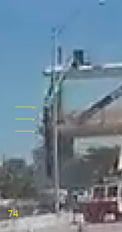
@MikeW7 - In frame 74 there is a spray of stuff at the north end of 12. Until now, I've taken that as artifacts. It only seems to be present for one frame with nothing significant appearing below it in the following frames. What is the general consensus? I haven't chased the other video copies yet.
 
Sym P. le (Mechanical) 14 Jul 19 03:20 said:
@MikeW7 - In frame 74 there is a spray of stuff at the north end of 12.
Are you talking about the new WSVN video? I noticed the one frame appearance/disappearance of the whitish cloud also, but didn't want to say anything that could color someone's impressions. Like I said when I posted the ZIP file, the WSVN video seems to much closer to an original copy than the GenFK version - larger file size usually means less compression. When a video is encoded, each frame is compressed much like the way a JPEG version of an original image is created. The dimensions remain the same, but fine details and subtle color differences are lost as more and more compression is applied.

ADD: The fact that it came from a news source rather than a random FaceBook account also means its more likely to be an original, or at least a high quality duplicate.
 
Sym P. le (Mechanical) Are you speaking of the white vertical lines? I think I see something in the same position relative to the tree in the previous two frames. If so, then it would obviously be part of the background.

SF Charlie
Eng-Tips.com Forum Policies
 
Here are two ZIP files that include earlier material from the ZIP file I uploaded in my post of 13 Jul 19 18:54 - the methodolgy is the same, except I've included frame 55 to 90 instead of 72 to 90. This allows you to watch the north end of the bridge as the background tree and foreground manlift/lightpole combine to created multiple distractions at frame 74.

EDIT: Well, the video actually starts at about frame 10, just as the bridge comes into view.
 
I tried different interpolation methods to upscale the video by 400%, and they all show the same thing: a big white & gray cloud that is partially obscured at the bottom by the infamous triangle that very much appears to be the NW corner of the deck. The upper part of the cloud is also visible in frame 73.
 
Status
Not open for further replies.

Part and Inventory Search

Sponsor