Eng-Tips is the largest engineering community on the Internet

Intelligent Work Forums for Engineering Professionals

  • Congratulations waross on being selected by the Eng-Tips community for having the most helpful posts in the forums last week. Way to Go!

Miami Pedestrian Bridge, Part XIV 78

Status
Not open for further replies.

JAE

Structural
Jun 27, 2000
15,433
US
A continuation of our discussion of this failure. Best to read the other threads first to avoid rehashing things already discussed.

Part I
thread815-436595

Part II
thread815-436699

Part III
thread815-436802

Part IV
thread815-436924

Part V
thread815-437029

Part VI
thread815-438451

Part VII
thread815-438966

Part VIII
thread815-440072

Part IX
thread815-451175

Part X
thread815-454618

Part XI
thread815-454998

Part XII
thread815-455746

Part XIII
thread815-457935


Replies continue below

Recommended for you

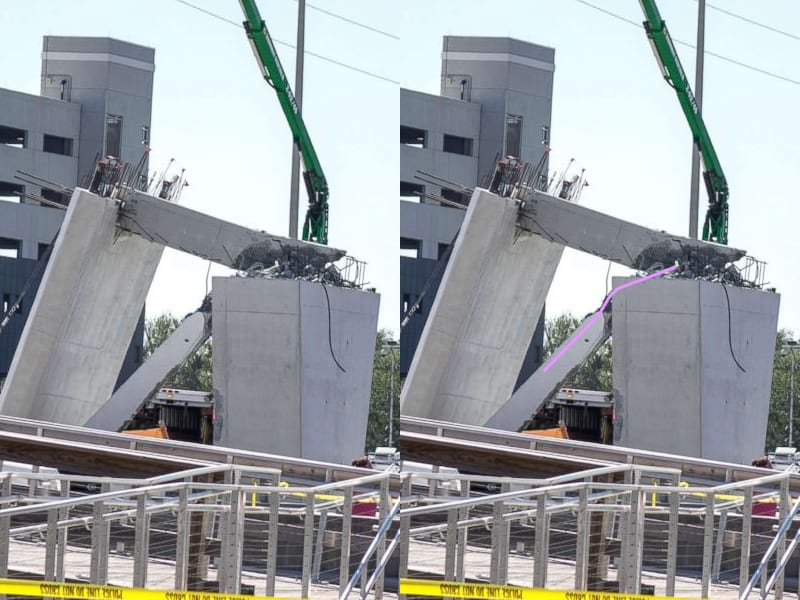
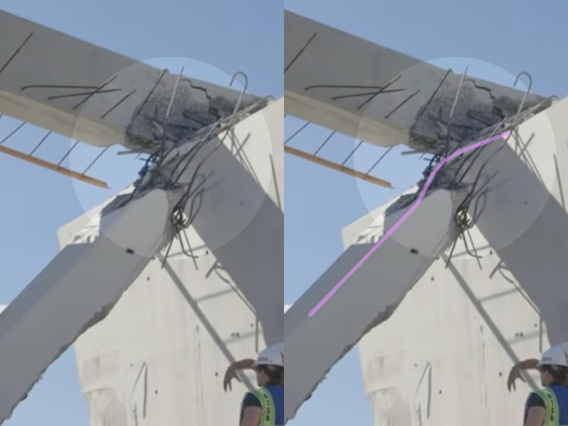
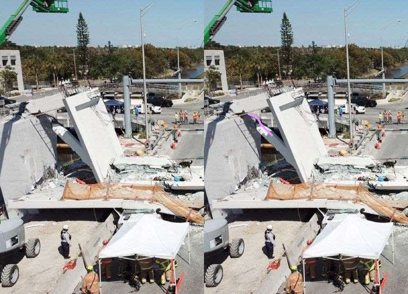
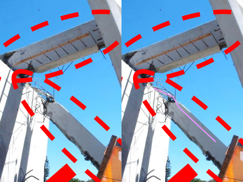
Five different vantage points of the upper PT rod in Member 11:

Photo1_hkhgh2.jpg


Photo2_ovkiqm.jpg


Photo3_qonde8.jpg


Photo4_e2flrm.jpg


Photo5_zg74ot.jpg
 
saikee, in response to your post, I submit the following:

What we should all appreciate is that the 11/12 node detached from the deck. The structure accommodated with various deformations and held (though momentarily) until shortly after load was reapplied to the two PT rods in Member 11. Whereas the design intended this node to be inclusive of the deck, it was not.

The detachment of the 11/12 node resulted in the lower anchorages of the PT rods having competing loyalties to the detriment of Member 11.

If Member 11 failed due to excessive load and offset ends (by deformation), the PT rods would unload their energy into the collapsed member (I believe the rods are stretched about 1.4") and then be vulnerable to deformation as the member crushed further. The different deformations of the upper and lower PT rods are consistent with this failure scenario. In fact, had Member 12(edit) the upper PT rod not deformed in this manner, it would disprove my theory.

If Member 11 pushed through Member 12, the lower PT rod would tear out of the bottom of Member 11 but Member 12(edit) the upper PT rod would be protected, at least initially.
 
Vance Wiley (Structural) 11 Jun 20 02:42 said:
i do not see an indication of failure of the upper PT rod in Member 11.

Interestingly, your posted image goes more to support my theory than a multitude of alternative perspectives. Your image indicates that the two deformations are in the same plane which is more indicative of a single assault than multiple assaults which might have occurred with the collapsing structure.
 
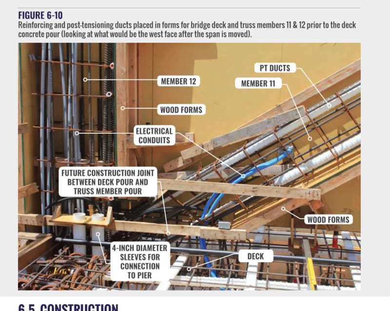
A picture is worth a lot of words.
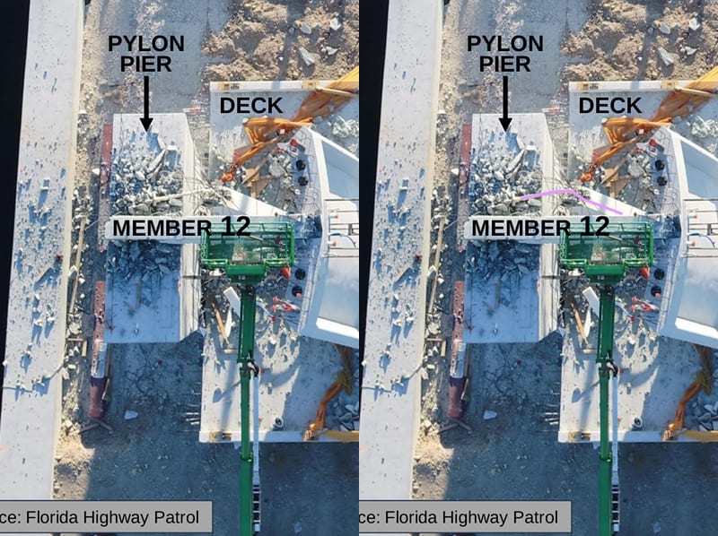
Is this the area which as supposed to be roughened?
Figure_6-10_omjmzt_lf9abx.jpg


The KISS principle applied to the failure.
Member 12; Negligible contribution to the structural strength.
Member 11; In compression.
The connection between member 11 and the deck; all of the calculations and speculation may be reduced to:
The connection will fail when the force on the connection exceeds X.
Member 11 is in compression and exerts a force of Y on the connection.
The upper PT rod is anchored such that it acts to add to the compressive force on member 11 but does not add to the force on the connection.
The lower PT rod is anchored in the deck.
Call the force on the lower PT rod Z.
Tension in the lower PT rod adds to the force on the connection.
When Y + Z exceeded X, the connection kicked out.

I can see the use of the PT rods to support the cantilevered portion of the span during transit, but once in place the rods were mostly superfluous.
Member 11 was under compression and the PT rods served to increase the compressive force, and in the case of the lower rod to increase the force on the connection.
The tension on the lower PT rod acted to open the crack rather than to close it.

All of the arguments and calculations come down to: When Y plus Z exceeded X, the bridge fell.
And it was done intentionally.

Bill
--------------------
"Why not the best?"
Jimmy Carter
 
waross,

The technical concept and ideas you are expressing are fundamentally correct. I would just say that it is better to say that the PT increased the concrete compressive stresses in member #11 or increased the shear stresses at the pour joint. I am being picky but the compressive force in the member was not increased due to the PT since the compressive member force is actually the sum of the PT (PT force is negative since it is tension) and the concrete (this is equal to the member force from the frame analysis). It is an important concept to think about the members this way when doing PT design.

Without any external forces, I can tighten a rod in a chunk of concrete and the concrete compressive stresses increase and the PT increases (in tension) but the chunk of concrete takes no more compressive load/force. It's member load or force is still zero. PT is equal and opposite to magnitude of the concrete.

When you think about post tensioned concrete or other residual stresses (tempered glass, wood shrinkage, cooling rolled steel elements etc.) in this way, it makes it less confusing/complicated and that is the only reason that I point it out.
 
Warros, you assert as a proposition:

"Tension in the lower PT rod adds to the force on the connection."

But this is wrong. By definition, the force "on the connection" is a force that is applied BETWEEN #11 and the deck. That means we are looking for a force OUTSIDE #11, that is BETWEEN #11 and the deck. This is the shear force between #11 and the deck. It is commonly agreed that this force was about 1,500 kips (1.5 million pounds.)

Note: tension in the lower PT rod is INSIDE #11. Therefore, it is not outside #11.

The bridge would have failed no matter what the tension in the lower PT rod. i.e. The failure condition of the bridge was independent of the tension force in the lower PT rod. Failure was caused by the fact that there was no tensile steel provided in the deck that could have prevented 1.5 million pounds in #11 from travelling north.
 
Is there some distinction between pure frames where joints are fully moment carrying and pure trusses where the joints cannot carry moment loads; perhaps semi-truss, where the joints will develop moment loads?

It is certain that this is neither designed as a frame, nor is it designed to avoid moment development which clearly caused a variety of cracks that a pure truss could not have.

I mention this as the linked Brady Heywood article calls this a truss; it's form is more of an openwork beam, not much different than if it had been first cast with a solid web that had triangles cut into it, rather than an assemblage of individual parts that normally comprise a frame or a truss. The main difference there is the localized web reinforcement to account for the loss of shear continuity from chopping so much out of the web.
 
Also - Brady Heywood is entirely wrong that parallel truss construction offers redundancy. The I-35W bridge was a parallel truss that lost a connection on one side and completely failed. There is no way for a structure that shares loads across two members to survive the loss of one of those members due to the imposition of torsion loads that won't be supported and the secondary loss of that joining structure (often roadway) that destabilizes the remaining truss.

If there are examples where a truss member failed under load and the structure didn't collapse it would be interesting to see them, but just two doesn't seem to be enough.
 
40YE
The lower PT rod was anchored to the deck below the crack.
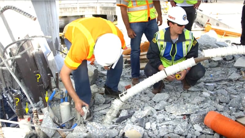
After the collapse and the destruction of a lot of concrete, the end of the lower PT rod appears to be still anchored to the deck, despite being ripped almost entirely out of member 11.
member12-11_rubble_on_deck_bjhslh_rsnb2u.jpg

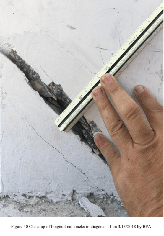
The crack is opening in a horizontal direction.
This strongly implies that the concrete had already separated and that the joint was held together by the reinforcement.
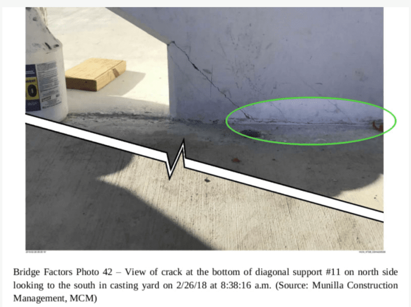
Here is the first indication of failure.
MCM_Fig_42_tflzm3_onqq7h.png


Bill
--------------------
"Why not the best?"
Jimmy Carter
 
3DDave, This is more of a truss. In reality there is no such thing as a pure truss but this is close enough that you can make a reasonable assumption for calculating loads. It is analyzed on a computer so it is almost irrelevant that we call it a truss or a frame because the computer accounts for the moment continuity at the joints. In the days before a computer analysis was so easy, this could be assumed to be a truss. Making a beam analogy is not so good. For beam analogies to work, plan section need to remain plane which is not the case here although the net bending and shear forces will be the same since this is very close to a statically determinant single span structure.

I agree, having trusses on both sides does not make the structure redundant.
 
OK, OK, ?
I'm confused. I thought that because the lower PT rod was anchored to the deck at the bottom, that tension in the rod created compression in the joint, but because the joint was not perpendicular to the PT rod, that a shear force was also applied to the joint? (Since the top of the upper PT rod was not exposed, I assume that it was not Post tensioned.) ((yes I know about assumptions.)

SF Charlie
Eng-Tips.com Forum Policies
 
Continuation of my post:
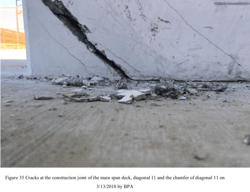
Here the crack is opening in a horizontal direction.
Yes, it's being measured diagonally but the movement is horizontal.
If the crack was opening diagonally, the horizontal crack to the right would also be opening.
The actual displacement is greater than the measured amount.
F40_r9yqtw_xr0f74.png

F35_dprcnp_rfnpvn.png

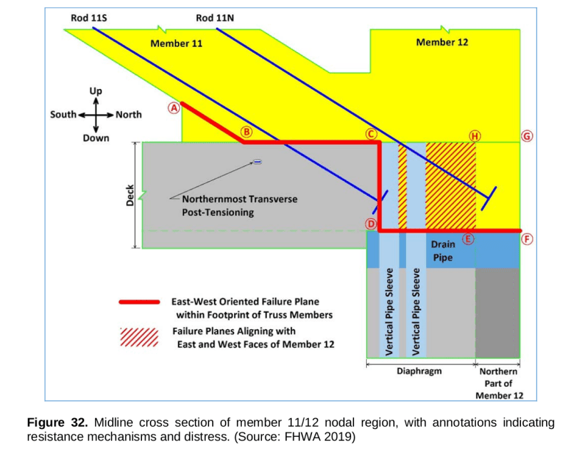
Looking at this sketch, the lower PT rod passes through the plane of failure.
The tension in the PT rod may be resolved into horizontal and a vertical components.
The vertical component adds to the friction of the failure plane but does nothing to close a horizontal crack.
The horizontal component of the PT tension acts to open rather than close the crack.
F32_laqfj3_jjmuau.png

Earth Pi said:
Without any external forces, I can tighten a rod in a chunk of concrete and the concrete compressive stresses increase and the PT increases (in tension) but the chunk of concrete takes no more compressive load/force. It's member load or force is still zero. PT is equal and opposite to magnitude of the concrete.(/quote)
The point is that one end of the lower PT rod is anchored outside of member 11 and did exert a force such as to cause the collapse.
Your comment is valid for the upper PT rod, but not for the lower PT rod.

The attempt to capture the node and to close the crack with a force in the opposite direction was particularly ill advised.
Talk about dumb and dumber.


Bill
--------------------
"Why not the best?"
Jimmy Carter
 
3DDDave,

In contrast with the previous answer you received to your question, I have always been of the opinion that the failure to recognize frame action was a primary reason for this failure. In steel trusses, you can sometimes get away with ignoring joint moments, due to the inherent ductility of steel. Not so with concrete, and that is why concrete trusses are exceedingly rare and not at all practical. This was a novel structure, and should have been tested before erection. A load test while it was still in the casting yard would have exposed its flaws.
 
3DDDave == "This was a novel structure, and should have . . . etc." Not true.

Trusses and frames have been around since before the middle ages. It is well known that both trusses and frames must have shear reinforcement at each node, where the forces in each element change direction. This particular truss/frame had no shear reinforcement in the deck connecting with the northward force in strut #11. Thus, the northward force in #11 kept moving northward. The rest is all hot air.
 
I suggest that you are all hot air, FYE. Or maybe you have a year experience, repeated 40 times.

Perhaps you can share with us an example of another structure of this type.
 
Wiki said:
A Howe truss is a truss bridge consisting of chords, verticals, and diagonals whose vertical members are in tension and whose diagonal members are in compression. The Howe truss was invented by William Howe in 1840, and was widely used as a bridge in the mid to late 1800s.
Is this part pertinent?
"whose vertical members are in tension and whose diagonal members are in compression"
So they took a design that was patented by a millwright over 175 years ago, pimped it up, failed to understand the basic forces and broke it.
I wonder if the drain, sleeves, and conduit were steel instead of plastic if it may have held together long enough for someone to condemn it without anyone dying.


Bill
--------------------
"Why not the best?"
Jimmy Carter
 
Nice point Waross. I quite agree.

Hokie 66 says "Perhaps you can share with us an example of another structure of this type."

Yes, every single truss/frame on the planet is a structure of a similar type. Every single truss/frame on the planet has got shear reinforcing at EACH NODE - because EACH NODE in a truss/frame necessarily connects a force in compression with a force in tension or an opposing force. This Miami truss/frame has got, effectively, zero shear steel at the node connecting the compression force in #11 with a tension force in the deck (north force in #11 with south force in deck). If you assert that it does have such shear reinforcing, please point out where it is.
 
We are talking about a concrete truss/frame here, not steel, cast iron, wrought iron, wood, or aluminum.

Howe, Pratt, and Warren are the most common configurations of trusses, and they are all commonly used in steel trusses.

There have been few, very few, examples of concrete trusses, mostly in Europe. I know of one concrete truss footbridge in California, now abandoned.
 
I think the point here might be that there were no gussets as there would have been in a steel truss.
Also FIGG proposes that it would be like an I beam.They seem to have forgotten that in an I beam the flanges are welded to (or rolled with) the web?

SF Charlie
Eng-Tips.com Forum Policies
 
Status
Not open for further replies.

Part and Inventory Search

Sponsor

Back
Top