Eng-Tips is the largest engineering community on the Internet

Intelligent Work Forums for Engineering Professionals

  • Congratulations waross on being selected by the Eng-Tips community for having the most helpful posts in the forums last week. Way to Go!

Miami Pedestrian Bridge, Part XIV 78

Status
Not open for further replies.

JAE

Structural
Jun 27, 2000
15,433
US
A continuation of our discussion of this failure. Best to read the other threads first to avoid rehashing things already discussed.

Part I
thread815-436595

Part II
thread815-436699

Part III
thread815-436802

Part IV
thread815-436924

Part V
thread815-437029

Part VI
thread815-438451

Part VII
thread815-438966

Part VIII
thread815-440072

Part IX
thread815-451175

Part X
thread815-454618

Part XI
thread815-454998

Part XII
thread815-455746

Part XIII
thread815-457935


Replies continue below

Recommended for you

Vance W.,

The north end of the bridge falls faster than 9.81m/s^2. It is not a free falling object. There is a rotational force added by the south pier which makes the north end accelerate faster. That is why the falling person is "slower" than the north end of the south segment. This is not intuitive at all that the north end is actually accelerating faster to the ground due to the south support. The CG of the south bridge segment is falling at a lower acceleration than 9.81 m/s^2. And obviously the south end of the south segment has zero vertical acceleration.
 
For a very straight forward example, consider a simply supported rigid horizontal beam, length L, mass per unit length m.
Kinetic energy = KE = 0
Potential energy = PE = 0
Instantaneously remove one of the supports.[ ] Beam begins to rotate downwards.

When it has rotated by an angle R it has rotational velocity Q and
PE = -mgRL[sup]2[/sup]/2
KE = Integral of [m(Qx)[sup]2[/sup]/2] wrt x, from x=0 to x=L.
These two must sum to zero, leading to
Q = sqrt(3gR/L)

If the falling end was accelerating downwards at g, the beam would have
Q = sqrt(2gR/L)
So the free end is accelerating at greater than g.

(Not that this ~20% difference explains the much larger difference that tweaked Vance W's interest.)
 
I reckon though that this blog misses a trick. It implies that the failure is due to concrete being in tension.

The real reason that we all know is that the member in compression, as it should have been, member 11, just wasn't attached to the lower part of the truss - the deck - with sufficient strength / re-reinforcement. The joint area at the deck, 11 & 12 node was not provided with enough steel to be able to connect member 11 to the bottom deck. The drain pipe, those 4 white plastic tubes and a host of other small black tubes plus the PT rods and their plates made it virtually impossible for member 11 to be connected to the deck with enough strength. THAT is the key issue with this concrete truss.

Now it's a bit of what iffery here, but IF those temporary tendons in member 11 hadn't been there would there have been more room for some steel to connect member 11 to the deck? Who knows?, but it won't have helped. Normally you wouldn't need to have 2 PT rods and their plates in such a truss. A bit like why those white plastic tubes were moved from somewhere where they caused no problem right into a highly congested location which again prevented sufficient steel from being included in that high stress area.

One layer of hole in the swiss cheese gone.

Add in that concrete trusses on their own may have worked as you could pour them in one go on their side to avoid all these horrible cold joints is a major downside to concrete trusses built into a slab / deck. Add in the cold joint was at a shallow angle to the compressive load and there's your hole in the swiss cheese appearing again.

Remember - More details = better answers
Also: If you get a response it's polite to respond to it.
 
Denial (Structural) said:
(Not that this ~20% difference explains the much larger difference that tweaked Vance W's interest.)
Thank you, DENIAL, for your time and your perception. At this point I do not remember ever doing the calculation you presented. After all, structures as such are not supposed to move. I did have to check a quite intricate mobile having at least 3 cross arms - one main and two suspended - with many hanging spires and about 20 feet in height from point of suspension. The point was to ensure that it could not impact any surfaces under anticipated seismic motions. As you know, even a simple 4 piece pendulum can require a very involved analysis, but the powers-that-be agreed that it could not displace farther than if it were rigid so I went to that limit first.
As a quick check, I normally go to limit conditions - even more so than your rigid and uniform beam assumptions. In my check for the time of fall I used the parameters of a point mass at center of span, weightless and rigid structure, and removed the north support. It seems to me under those conditions the north end would fall at the rate of 2g and the nuances of the problem could only slow the fall. Under these "ideal" conditions the fall distance at the north end becomes just less than 6 feet in 429 milliseconds.
In the actual case at hand, previous calcs found the north end was on the pylon until Node 9/10 dropped about 10 feet. As the deck folded somewhere near Node 9/10 the yielding of the PT in the deck maintained its moment capacity, however inadequate, and effectively slowed the collapse to some extent. The canopy also provided some resistance.
So my takeaway is that this collapse took much longer than 429 milliseconds and even the experts can benefit from a review of their work.
I agree with Charlie's suggestion that an incorrect frame rate was likely used.
Thanks again,
 
I think we're splitting hairs here guys. OK less than half a second is a bit too fast, but one second - who really cares? The point is that is was so fast when it finally went no one had any time to do anything, either the poor buggers under it or the equally poor workers on top of it.

I still think this bridge got so much attention because of that dash cam footage being posted so soon after the collapse.

Remember - More details = better answers
Also: If you get a response it's polite to respond to it.
 
One takeaway from this latest round of hair splitting is that now it's clear that the bridge literally fell out from under the people working on it. They didn't ride it down. It pulled away out from under them at greater than 1g, and they landed in its wreckage.
 
Vance Wiley (Structural)1 Jul 20 16:51
The times and the state of the bridge are from the NTSB report (pages 11,12) (sheets 30,31 of 152 in the pdf)
Link"Highway Accident Report
Pedestrian Bridge Collapse Over SW 8th Street
Miami, Florida
March 15, 2018" figures 9 and 11


SF Charlie
Eng-Tips.com Forum Policies
 
In furtherance to my previous posts, I submit the following as the final straw which led to the cascading collapse. I will not backtrack through shortcomings in my previous posts nor reiterate the strengths of my arguments. I do not submit to the fallacy of a concrete blowout.

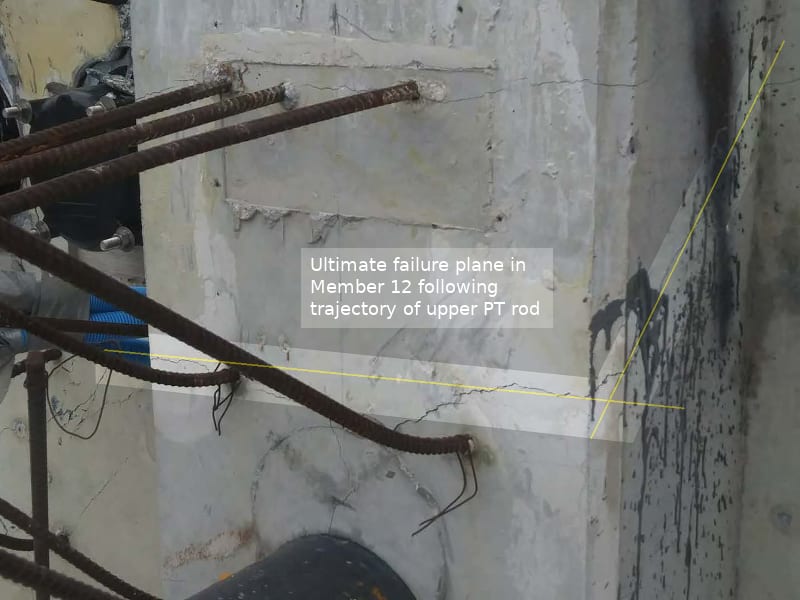
Member 12 ultimately hinged along the failure plane tracking the upper PT rod. The following image labelled "PHOTO 8: Truss 12, North view cracks" from NTSB's Bridge Factors Attachment 24 – Email from Mr. Rodrigo Isaza of MCM to Mr. Dwight Dempsey of FIGG dated March 12, 2018 is indicative of such failure.

I suspect this explanation will resonate with most.

Ultimate_failure_plane_Member_12_wcmpoq.jpg
 
[quote=LittleInch (Petroleum)1 Jul 20 17:16 I think we're splitting hairs here guys. said:
[who really cares?]
You are completely correct - the time it takes to fall makes no difference in the outcome of the collapse or those damaged or lives lost.
But - if the expert makes this mistake in front of a jury and is called out on it he loses credibility and likely his influence in the case.
Now SFCharlie tells me the time is from the NTSB Report? This just keeps getting better. Maybe someone should carefully review the NTSB report. Was the time stamp made by the camera taking the video or assigned during some viewing/editing process? At any rate (oops - no pun intended) the interpretation is easily misleading.
The math presented in the BLOG is correct as to differences in time presented by the NTSB and apologies become due to the BLOG.
I will trust that the author prepares in more detail before testimony than before blogging.
Thanks for the link, SFCharlie.

 
The full frame un-interpolated dashcam video is available on YouTube at Link. The start of the collapse is about 23 seconds in and the on screen time is displayed in seconds (not microseconds). Those of you with download and frame by frame software can have fun. I watched it at 1/4 speed and can get about half second resolution. After one second the bridge has not hit the road.

SF Charlie
Eng-Tips.com Forum Policies
 

I just did a FBD with a rigid horizontal stick supported one end. Acceleration varies linearly from zero at one to max at the free end. I get an acceleration of 1.5g at the free end, 0.75g in the middle. The load at the support is 0.25wl. Hopefully I didn't make any mistakes.[glasses]
 
Despite my better instincts, I downloaded the video, loaded it into VLC player, went to 23 seconds, counted frames per sec of on-screen time (5fps), single stepped forward to ejecta and movement (about 19.0-19.2 on-screen time) and then to deck hits the street (about 20.2 on-screen time)

SF Charlie
Eng-Tips.com Forum Policies
 
EarthPi.[ ] If you made a mistake, I made the same one.[ ] Taking my workings one step further gives a starting acceleration of 1.5g at the free end.
 
Sym P. le (Mechanical) said:
I do not submit to the fallacy of a concrete blowout.

In reinforced concrete a blow-out is a loose term. Generally it means when a part of the reinforced concrete under a very stress suddenly fails the local concrete is crushed into small pieces and disintegrated after the collapse.

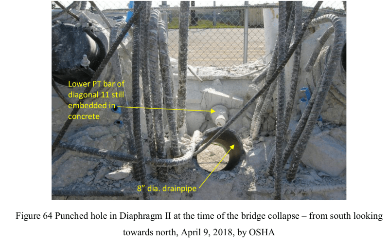
OSHA is an officially appointed and professionally qualified investigator in the FIU bridge collapse and the word blow-out has been used in the report text five times and in the description figures also five times. NTSB used the word blowout also four times in the text and one time in the figure description. Thus the word blow-out or blowout would be the opinion of an expert witness in court and one I would concur based on having worked all my life with reinforced conceret. Thus I am sure it isn't a fallacy.

Comparing your figure posted on 1 Jul 20 17:57 with OSHA Fig 64 below (or any of Fig 58 to 70) your ultimate failure plane is nowhere near to what had happened on the bridge.

F64_nyve4g.png


The bottom of 12 failed because the weakest plane, where the stress is the highest when the cross ection is the smallest, is at the 8" PVC drain and not somehwere above it where Member 12 still has a full cross section. The OSHA Fig 58 to 70 inclusively show no concrete above the 8" drain after the collapse.

The elastic mudular ratio between concrete and PVC is about 15:1 so the 8" PVC pipe could take hardy any laod. If both deflect by the same amount the PVC takes only 1/16 of the load when both have the same area. However the overall 8.6" OD PVC drain caused a 41% reduction in the 21" thickness of Member 12. As the drain pipe situated at the middle so the reduced section is split into two 6.2" thick pieces on either side of the PVC drain. Do you still think the 21" thick concrete is easier to break than two 6.2" sections when under the same load?

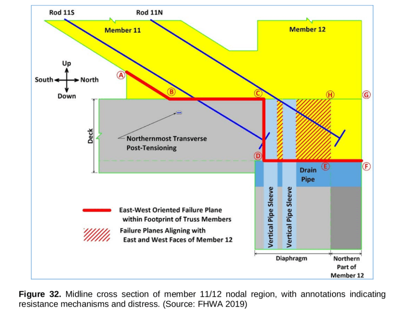
Lastly I like to re-post NTSB's Fig 32 below as this is the official failure plane concluded by NTSB and it matches all the post collapse photos. Any attempt to re-write the history or the offical verdict should be supported with similar rigorous analysis and investigation. Merely a personal opinion on something else not backed by proof is not a contribution to our understanding of what has really happened.

F32_jxmer6.png
 
Thanks again Saikee for your discussion. I have a response but it will me take some time to put together.
 
Hi Saikee, much appreciated. But I have a question. Because failure is a three dimensional event, there must also be a vertical failure plane. Your excellent diagram shows only a failure plane in a horizontal plane - red line extending in an out of the page to form a horizontal plane. Can you clarify ? Many thanks.
 
FortyYearsExperience (Structural)

With reference to NTSB Fig 32

Along the South to North direction

The failure section has A-B-C and D-E-F in horizontall direction. A-B-C failed by shear but D-E-F was likely by bond failure as the none of the reinforcement (2x#11+8x#7 on East and then on West face) failed by shear. The vertical plane C-D failed by tension. In reinforced concrete design concrete is assumed no tensile resistance in design and a small amount in analysis.

Along the East to West direction (East being Fig 32 while West is the back side of 11/12)

The deck is physically attached to 11/12 via area C-D-E-H-C but the two 4" dia vertical pipe sleeves destroyed part of the bonding or shearing area. What was left has been indicated by the hatched area and there are two sides both of which failed by shear.

 
Hi Saikee
Sounds interesting, but confusing. Any chance you can provide a plan view of the deck showing what you consider to be the vertical failure planes ? many thanks for your input.
 
Status
Not open for further replies.

Part and Inventory Search

Sponsor

Back
Top