Continue to Site

Eng-Tips is the largest engineering community on the Internet

Intelligent Work Forums for Engineering Professionals

  • Congratulations KootK on being selected by the Eng-Tips community for having the most helpful posts in the forums last week. Way to Go!

Pedestrian truss "pony truss" 10

Status
Not open for further replies.

Gus14

Civil/Environmental
Mar 21, 2020
186
My boss wants a pedestrian truss like shown in the attached picture to support 6 meters long floor beams {W 5*16). He wants the pedestrian bridge because it can serve as a hand rail and not decrease floor clear height. I did the analysis and found that the maximum axial load in the top chord 100 kn in comp and in the bottom chord 100 kn in tension. I chose section HSS (2*2*3/16) for top, bottom chords, diagonal and verticals FY IS 50 ksi. After revising the AASHTO GUIDES for pedestrian bridge i found that I need to weld another ( HSS 2*2*3/16 ) to prevent top chord buckling and be conservative.

1) in the ASSHTO guides stats the following : the connection to the floor beam to the vertical shall not include the HSS chord member, i.e. the vertical and the floor beam shall not be connected to different sides of the HSS chord.
SO WHERE SHOULD I PUT THE BOTTOM CHORD IS IT POSSIBLE TO PUT IT ON TOP OF THE FLOOR BEAMS AND HOW FROM THE INSIDE OR OUTSIDE or in between verticals ?

2) I really have no idea how to design the gusset plate connection any simple reference would be very appreciated. And any conservative answer is also welcomed.
 
 https://files.engineering.com/getfile.aspx?folder=ad7a82ec-4530-4f6b-8635-56f57c88f11c&file=2.pdf
Replies continue below

Recommended for you

The code statement you referenced about framing into the bottom chord was placed there by yours truly (via appropriate correspondence with the AASHTO committees). The problem with framing the floorbeam into the bottom chord is that the chord will "ovalize", as shown in KOOTK's post and referred to as "racking". The floorbeam should frame into the truss vertical for maximum stiffness. You can also frame the floor beam below the bottom chord ( we commonly call this an underhung floorbeam) but you loose about 10% of stiffness in the connection. (Stiffness being the spring constant "C" value calculated with an average/typical size pedestrian bridge).
 
Thanks for chiming in TrussBridgeboy. It's great to have someone of your particular expertise on staff here.
 
I have to ask - At only 6m spans and 3kPa dead, 3kPa live.. why are you using trusses at all?

I would have expected a nice standard beam section to work here? Also, with verticals at 400mm crs and intermediate diagonals, by the time you draw this truss to scale I think its going to look very heavy. Perhaps I’m missing something?
 
I worked for a company where we engineered and fabricated pony trusses on a near daily basis.

I don't recall if AASHTO covers this, but be sure to calculate the K Factor for the top chord. I've got a paper on it at work, I'll try to dig it up. In short though, the K Factor is likely to be greater than 2, and if you don't account for it, you will undersize the top chord.

For the verticals/diagonals, we always used members that we're smaller than the bottom/top chords. For instance,

Bottom chord = HSS 6x4x1/4 LLV
Verts and diags = HSS 2x2x1/4

That will allow you to get a fillet all the way around and forego the gussets.
 
A follow up

If you only intend to use the sides and guardrails, and if you don't intend to rely on them for strength, I recommend not including them in your model. They will contribute stiffness to the model. If that's the case, just treat them as point loads.

If you don't account for the K Factor as noted above, and if you're not certain about the connections, then it's possible the top chord could potentially blow out and make for a bad day at the office.

And lastly, don't forget to account for ice!!!
 
Pardon my ignorance of the US codes - but what is the K factor you refer to above? I’m wondering if this is what we over here call the C factor! Roll on GloboCode!
 
The K-factor is the multiplier that you'll put on the member length to transform your real buckling problem in to an equivalent, pin-pin, Euler buckling load problem.
 
MIStructE_IRE - K factor gives you the effective buckling length of the member compared to the base condition of pin-pin supports and also with a concentrated load applied at the ends. In this case the compression member is braced intermittingly by spring supports and does not have uniform compression. To get the effective K factor in this case you would calculate the actual buckling load of the member and back-check to see at what length the same section would buckle if it was pin-pin supported with a concentrated load. For a reasonably proportioned pony truss I think this usually works out to be in the range of 2x the floor beam spacing.

Gus14, 6m sounds like a long span for a W150. You've shown your strength check, have you checked these members for deflection? I think the diagram posted by BAretired and KootK's followup messages are good enough reason to ditch the W150 in at least a few locations - you need a stiff floor beam and a rigid connection the truss vertical in order to provide lateral stability for your top chord.

I think MIStructE_IRE has the answer anyway - truss seems overkill for the spans, just size a beam to span the 6m. It will be vastly more economical than the truss - the savings can pay for a very nice handrail.
 
Thank you everyone for info I will cantilever the columns up above the deck to restraint the top chord every 5.5 m and size the top chord. (I forgot to mention it)

I sized a beam before the truss (it was 20 cm) and still the clinent complained. So the boss suggested a truss.
 
I did the calculation on 5.5 meters span top chord (because the top chord is braced at columns locations and K factor was reasonable. Please correct me if I'm missing something..
 
A Follow up
I did check deflection and it was 7 cm I was so desprate to find a section I stopped caring. I'm kinda fed up with the client he is demanding and cheap so I will let my boss handle him. 🙂🙂
Better stay away than sorry
 
Gus14, 70mm is a significant amount of deflection on a 6m span (L/85).

I don't want to discourage you because it is clear you're putting in the effort to figure this out - but it appears you're over your head here and need some more direction from your boss. In one direction you're using a shallow W150 to span 6m and in the other direction you're using a truss to span the same distance. Clearly the truss and floor beams are carrying different loads, but just from a span/depth perspective, one is way oversized and the other undersized.
 
Yeah like I said I gave my boss the analysis results and the large amount of deflection and he said he will handle the deflection somehow. He insisted on the truss. Hopfully all goes well if it doesn't not my decision to call..
 
Is the truss simply supported? If so, try fixed ends to reduce the deflection.
 
A continuous truss with a Span/depth ratio of 6, even at the elephant shoe fitting factory, should not be deflecting 70mm! Certainly not when its supporting 3kPa. There’s something not adding up for me here.
 
Whether simple span or continuous, a one meter deep truss is not going to deflect 70mm on a 5.6m span.

From all of the above, it's difficult to know what the client would be prepared to accept. If headroom is the issue, why not raise the whole thing to accommodate the required headroom?

BA
 
You guys misunderstand the framing here. The full picture is scattered through thread. The truss spans 6m, but they’re also spaced 6m apart. Framing between the trusses are the W150 floor beams - these are deflecting 70mm over 6m.

If you’re going to span floor beams 6m then turn them the other way and span them 6m in the direction of the bridge. You can use a girder spanning between your original truss supports - this space was occupied by some sort of foundation structure before so you should have clearance to drop the girder below the deck level without taking up usable space.
 
The floor beams are W5x16 (Imperial?) spaced at 400mm centres and span 6m between trusses. The beams are rather shallow for a 6m span. They are too close together for economy, but the deck material has not been specified, so who knows?

It would make more sense to use deeper beams spaced at about 2m spanning between trusses and modify the truss panel points to match the beam spacing. Alternatively, a beam could be used in lieu of a truss with a simple handrail mounted on top. Whether or not this would satisfy the client is anyone's guess.


BA
 
Yes imperial. Steel is rarely used in my country of residence so I dont have much of experience(as if you have not noticed already). The deck is shaker plate. How much far can you span floor beams ?
The client doesnt want more than 14 cm depth so not much I can do about it.
I think some welder convinced him that it can be achieved but I can't justify the numbers.
 
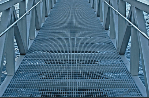
A bar grating would be another alternative (see below). For a width of 6m, you really should come up with a better framing plan than 5W16 @ 16" centres. The beams should be deeper and spaced further apart for economy. A spacing of 400mm (16") is not reasonable.

The client needs to give you the freedom to design the structure in a way that makes sense.

image_bffzad.png


BA
 
Status
Not open for further replies.

Part and Inventory Search

Sponsor