Continue to Site

Eng-Tips is the largest engineering community on the Internet

Intelligent Work Forums for Engineering Professionals

  • Congratulations SSS148 on being selected by the Eng-Tips community for having the most helpful posts in the forums last week. Way to Go!

Y14.43 Gaging Question

Status
Not open for further replies.

dthom0425

Mechanical
Dec 6, 2018
47
Hi all,

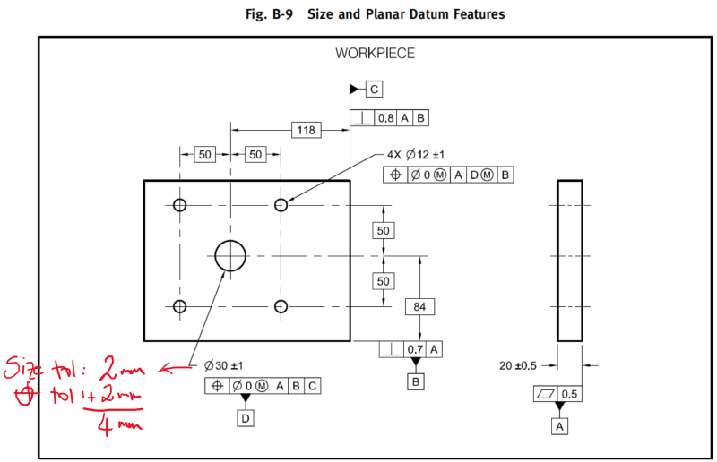
I have attached a photo from ASME Y14.43 (Figure B-9). I was going through some of these examples in this appendix and I'm a little confused with the outcome of this one.

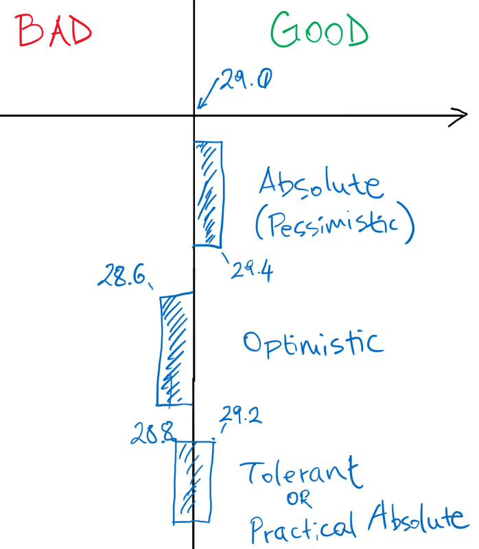
To inspect this part with a gage, I was expecting the gage to utilize a fixed pin set at 29mm to gage datum feature D. The example in the spec actually shows the fixed pin to be 29.2-29.3 mm using absolute gaging policy.

Am I missing something here? I thought absolute gaging policy was pessimistic and worst case (meaning 29mm not 29.2).

Thank you
 
 https://files.engineering.com/getfile.aspx?folder=be11edad-5e83-4da9-aeb3-99b50fa99466&file=fig9.JPG
Replies continue below

Recommended for you

Plus / minus 1 for the part size meaning total size is 2mm.
29 is the nominal gage size. On this nominal gage size you have to apply the appropriate gage tolerance which is 10% from 2mm resulting in the gage size tolerance of 0.2mm.
29mm nominal then apply the absolute gage tolerancing policy
 
dthom0425,

You need to check the size of the hole and the position of the hole. So you would need 2 sets of gages:

1) GO / NOGO gage for the hole size... GO pin would be 29 +0.2 / 0... you may reject some good parts, but never accept bad parts

2) a functional gage for the position callout. You will have a different pin size on this gage.

So in that example. The pin has :​

IB = 29.0​
OB = 29.4​

So the tolerance for the pin is 0.4, which is exactly 10% of the workpiece (4 mm).​

Similar to the GO gage for the size tolerance... You may reject some good parts but never accept bad parts.​

 
Tarator said:
which is exactly 10% of the workpiece (4 mm).

Would you please advise what the 4mm is, I can't find it out on the workpiece.

Season
 
SeasonLee,

Here it is:

B-9_fy2nbu.png


You could also adjust your gage so you end up with total tol 0.2 mm instead of 0.4 mm just for the POS tol portion (since this gage is only for POS callout)... There are some examples like that in the same standard.

Also, the main thing is that you will need 3 gages:

1) GO gage for the size,
2) NOGO gage for the size,
3) Functional gage (GO) for POS callout (at MMC), for Hole's IB (=VC)
4) Note: In case you are curious, for Hole's POS variation at LMC, any functional gage would be inside the material, so it is physically impossible. You would need an Xray machine. However, you wouldn't need to check that anyway as 2) and 3) take care of this. In other words, if 2) and 3) pass, then 4) would pass also. To give you an example, if 2) passes (Size and Rule #1 boundary pass), but 3) does not pass, then it would mean that the POS variation was too much (out of spec). Why would you check the POS again with 4) ?
 
Tarator,
How the optimistic tolerancing would look like?
What about tolerant tolerancing?

 
Status
Not open for further replies.

Part and Inventory Search

Sponsor