Eng-Tips is the largest engineering community on the Internet

Intelligent Work Forums for Engineering Professionals

40-ton timber arches collapse in Hickory, NC 35

Status
Not open for further replies.

bugbus

Structural
Aug 14, 2018
498
0
0
AU

Before:
c_v0gdsn.jpg

a_xq7ujk.jpg

b_bjiumg.jpg


After:
3_idudj9.jpg

2_cygatg.jpg

1_scwfo5.jpg
 
Replies continue below

Recommended for you

My VPN allows me access to many countries sometimes...

Rather than think climate change and the corona virus as science, think of it as the wrath of God. Feel any better?

-Dik
 
If you look at Western Wood Structures portfolio ( [URL unfurl="true"]https://www.westernwoodstructures.com[/url] ) as well as some of their YouTube videos, they use this type of pin connection quite a bit, through this arch uses the 'lightest' example of it that I have seen. I suspect it is used in dealing with the expansion/contraction of their structures.

None the less, Western Wood Structures is pretty clearly not a run-of-the-mill 'design' firm as they have some simply phenomenal structures across the world (some of which I've seen in person) - which makes this arch creation (and failure) all the more baffling.
 
It is hard for me to tell with the grainy security camera footage (seems to be a staple here at eng-tips...), but it sure looks to me like the tip started to fail first and then overloaded the lower fixed "hinge" points causing them to fail and twist as it rolled over.

I cannot imagine it would take much horizontal load on that single pin joint at the top to cause it to tear out as it appears in gusmurr's earlier post.
 
Maybe the lower part is intended to be fixed?

Rather than think climate change and the corona virus as science, think of it as the wrath of God. Feel any better?

-Dik
 
Those cables definitely look decorative, with the way they're attached and the angle. I guess they were just tensioned enough to look good. So what was supposed to be stopping it from blowing over?

As soon as that failed and it started going, it would have put the windward side cable under massive tension and it would have pinged, which looks like what happened in the pics where you can see the broken cable. But that's a symptom not a cause imo. Looks like those crossover joints half way up just weren't up to the job.

EDIT: posted this before seeing the vid. It looks like this halfway up hinge failed on one side, that side then dragged the other half down and that would have pulled the cable as well.
 
dik (Structural) 22 Feb 22 16:20 said:
The gif is neat, but did anyone notice that degree of motion?

Thanks for the neat comment but I think you missed the point. The gifs only purpose was to convey the idea of the freedom of movement, full stop. What might be obvious (and may not) is that once any movement starts, other factors quickly come into play and complicate the collapse sequence. I for one am not ready to meld half a dozen or more factors into one animation, let alone fine tune it to inches or less. The gif was neat but it's also wrong (I fear) and not because it moves south instead of north or moves to far. Much to my dismay, I finally took a closer look at the math of the guy wire and realized I was out to lunch, or should have just had lunch instead. In order for that gif motion to occur, something else had to break first (the guy wire or another connection).

TugboatEng (Marine/Ocean) 22 Feb 22 07:27 said:
... perforated metal strips must have been the repair as they're not visible in other images ...

Thanks for posting, I was looking for images relating to the repair or where the crew may have been working at the time but had not found any. That flimsy repair may be the key. A closer analysis of the videos just posted may reveal that leg buckling first.

I believe it's the connector of the lower arch on the east end of the structure. In the closeup, the timber to the right of the connector is of the upper arch. Only a fragment of the lower wishbone remains. That southeast leg fell off and under the bridge.

Repair_Zone_ub8jgn.png


Repair_Zone.02_kqht10.png
 
Red Corona said:
Looks like those crossover joints half way up just weren't up to the job.

Seems like it. They needed to be rigid to prevent 5 hinged arch formation, and also to prevent it falling over laterally like it ended up doing.
 

The gif may have obscurred or detracted from the failure. Movement would be nowhere near that magnitude, and people seeing the clip might be expecting that type of failure.

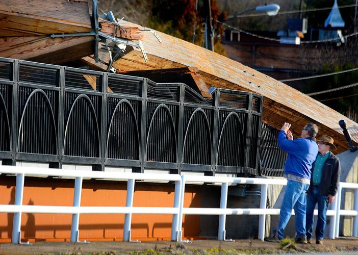
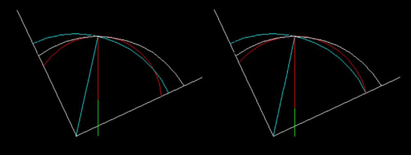
Failure did not appear to be from a cyclical loading. From the clip posted by Hokie, it appears that there was no movement due to wind and that the one cable may have failed, allowing the top of the arch to fall to the right, bringing down the 'fixed' base parts. All is speculation; it's a matter of 'those in the know' posting the real cause of the collapse.

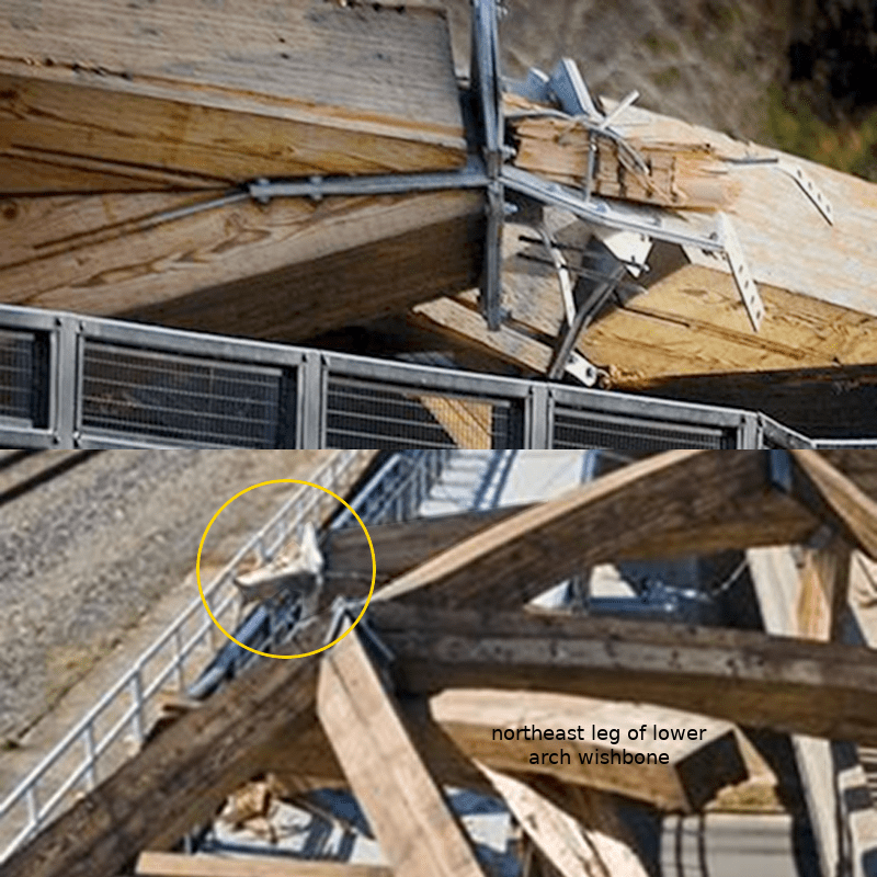
It would be nice to see the failure parts to see how the components fared... I suspect strongly that the one cable 'snapped' for whatever reason. Cable failure may have precipitated the collapse, or some component/connection failed causing the overload to the cable. I suspect that the one cable is 'broken', but I don't know for sure.

Rather than think climate change and the corona virus as science, think of it as the wrath of God. Feel any better?

-Dik
 
dik said:
Movement would be nowhere near that magnitude, and people seeing the clip might be expecting that type of failure.

The failure looked pretty much like that from the first video. Isn't that all the gif was saying likely happened? That the top fell over? I didn't think he was saying it looked like that in service. Merely that it looked like that when falling over.


The wind was blowing in the video. Flags near horizontal. So likely it blew over in the end.
 
I just discovered that the location of the elevated hinges may have contributed to the collapse. Take a gander at the sketch. By elevating the hinges, the extension to the cable can be minimised so it offers little lateral resistance. That may be the cause.

Clipboard01_ty8avb.jpg


The blue is the trajectory of the cable and the red is the trajectory of the crown of the arch from the elevated 'base'. The white is the trajectory of the crown of the arch if the rotation were about a non-elevated base. The difference in the two schemes is the location of the elevated base.

Rather than think climate change and the corona virus as science, think of it as the wrath of God. Feel any better?

-Dik
 
yes, the red thing and the red trajectory... nearly matches the blue cable trajectory. The white shows the extension to the cable required if the base of the arch were at the bottom, and not elevated to the point at the intersection of the green and red vertical line. The cable may not even be broken. I'm just trying to show that the cables may have been totally ineffective, or seriously compromised. the white lines starting from the base of the cable are 'trim' lines only for cutting the circle circumference. [pipe]

I just realised that in the Right Sketch, the cable is in tension. In the Left Sketch the cable is mostly partially in compression and the first rule of engineering is that you can't push on a rope... maybe we've solved the manner of collapse.

Rather than think climate change and the corona virus as science, think of it as the wrath of God. Feel any better?

-Dik
 
Status
Not open for further replies.
Back
Top