Continue to Site

Eng-Tips is the largest engineering community on the Internet

Intelligent Work Forums for Engineering Professionals

  • Congratulations KootK on being selected by the Eng-Tips community for having the most helpful posts in the forums last week. Way to Go!

Customized DRF instead of a Translation Modifier 1

Status
Not open for further replies.

Burunduk

Mechanical
May 2, 2019
2,354
During a recent discussion that developed in thread1103-501700 , claims were made that at every place where the Translation Modifier is used, the Customized Datum Reference Frame tool can be used instead.
Here is an excerpt of the argumentation:

3DDave said:
The point is that customized datum reference frames are a proper superset of which the translation modifier is a tiny part. That there is no function available via the translation modifier that is not contained within the customized datum reference frame capability. That the control of acceptable variation by the more capable approach is identical to the more limited approach with the correct syntax.

Other opinions that were expressed suggested otherwise:
Evan said:
In some cases (such as the plane-hole-slot case discussed earlier in the thread) the same DRF can be achieved using either tool but this is not true in the majority of cases.

I'm interested in clarifying the issue.
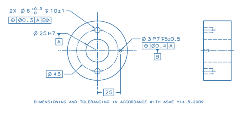
Below is a drawing example that uses the Translation Modifier tool.
The ⌀25H7 bore is the locating feature of this component in its functional assembly, and it also sets its initial orientation. It aligns to a mating shaft with a "sliding" clearance fit of H7/g6 (hole basis). The ⌀3P7 hole is intended to fit with a pin that will be assembled into it with an Interference fit of P7/h6 (shaft basis). The pin will contact a radial slot on the mating part to lock the rotation about the axis of the bore, to do the "clocking".
If you were to duplicate the effect of the Translation Modifier applied to datum feature B by using a Customized DRF, how would you go about it? What would the customized datum reference frame look like, and how would it override the default degrees of freedom constrained by datum features A primary, B secondary?
If you think this idea would not work and the translation modifier should be kept, please explain why.
I would appreciate everyone's opinions.
Thank you.
translation_mod._dwg._fzbed6.png
 
Replies continue below

Recommended for you

I thought you were going to do the drawing, not combing through textbooks of other people's work to find a topologically identical example to the one in the standard.
 
Textbooks of other people's work?
One could assume you wouldn't claim that unless you saw that example in the textbook it is copied from to support your accusation.
Unfortunately, that would be a wrong assumption.

It is my drawing. Made in CAD and visually adjusted in PowerPoint to give it the appearance I like.
Suggest any alternation, and it will be reposted with it tomorrow with that exact style with some portions remaining exactly identical to the original I posted above so that you can make sure it was not recreated. (I'm just out of work, that's why tomorrow).
 
Why 2009 then? That's superseded. I'm surprised it is your work with the non-conforming diameter leader. It's also sloppy to change the font height for dimension tolerances. That is also non-conforming, but a common erroneous practice. The note text height should also be the same as the dimension text height.

"Visually adjusted in PowerPoint?" What CAD system needs an assist from PowerPoint?

It is no different topologically from 2018, figure 7-12, as regards the translation symbol. There is an axis and a non-coaxial feature for clocking.

It also has the same defect as a mechanical part per Fig. 7-12 - simultaneously expecting a fixed location variable diameter mating part being inspected with a moving location variable diameter inspection, a conflict in requirements.

In this example that tolerance indicates more than 10% shear of the mating pin is acceptable.
 
"Why 2009 then? That's superseded."
Because the 2009 version doesn't include that ambiguous note under the TGC requirements section.

"What CAD system needs an assist from PowerPoint"
A matter of personal preference.
I can post the pre-PowerPoint version tomorrow if you wish to see the difference. Just ask.

Sorry for not making a perfect drawing and design.
I wonder how you made the conclusion about mating pin shear?
BTW, are you going to be on topic and write something to the point of this thread
 
I will try to be short.
In absence of modifier the simulators for both holes will be 2 expanding pins fixed in space within gage-makers tolerances, which is a pain in itself. (It was already discussed here to death)
In 2009 ASME suggested “simple” solution – the symbol to explicitly specify which one out of two pins can be let go. (Don’t have to be pins)
Almost immediately they realized it could be confusing, so in 2018 they added an option – to explicitly specify the axis along which the simulator can translate. (See Fig. 7-12(b) in 2018)
In our cases it will be [0,1,0]
Now, if we explicitly specify that simulator is NOT restricting a movement along axis Y, how is it different from explicitly specifying, which movements simulator DOES allow?
So, in my opinion, customized DRF will do the job.


"For every expert there is an equal and opposite expert"
Arthur C. Clarke Profiles of the future

 
 https://files.engineering.com/getfile.aspx?folder=abbe7ed2-3163-4982-98e0-ce6c343015f2&file=translation_mod._dwg._fzbed6.png
BTW, are you going to be on topic and write something to the point of this thread

Already did. This is the same topology as the example I cited. You could have used that.

Still, the basic ambiguity in the rules is this: The secondary datum feature here and the tertiary datum feature in Fig.7-12 both suffer from the rule that suggest by implication, not explicitly, how the clocking is to be determined.

For example, had the two 6mm holes been datum feature B and the 3mm hole used them as a secondary datum reference would the primary datum be considered as being involved in clocking the part, particularly if the translation modifier was used?

The correct thing to do, which the committee has refused to, is to make the tertiary control explicit as required; in your example that would be [A|A-Bt] (t for translation modifier) or [A<xyuv>|A-B <w>] for the customized datum reference frame.

You allow dia 0.4mm location variation on a dia 3mm pin. But why diametral if it's mating with a slot? More variation can be allowed in the radial direction and less, typically, in the tangential direction, which, if it was on the drawing, would allow the tangential control to be the datum feature, solving the problem and accurately describing the use.
 
CheckerHater said:
In our cases it will be [0,1,0]
Now, if we explicitly specify that simulator is NOT restricting a movement along axis Y, how is it different from explicitly specifying, which movements simulator DOES allow?
So, in my opinion, customized DRF will do the job.

The problem with the customized DRF that I see in this case, as I think you suggest, is this:
If we state the "customized" datum reference frame per [0,1,0], we will end up with:
|A[y,z,v,w]|B|
If we write the implied degrees of freedom each datum feature and simulator is responsible for constraining according to a non-customized feature control frame that references |A|B|, we would end up with A constraining y,z,v,w, and B constraining u.
So, if the explicit and implied are the same, what is gained by the use of a customized DRF, in this particular case?
 
3DDave said:
For example, had the two 6mm holes been datum feature B and the 3mm hole used them as a secondary datum reference would the primary datum be considered as being involved in clocking the part, particularly if the translation modifier was used?

You lost me right where the primary cylindrical datum feature became associated, of all things, to clocking. Can a cylindrical primary datum feature constrain the rotation about its axis?
 
Burunduk,

I can't think of a customized DRF that duplicates the effect of the translation modifier in your example. Cylinder A constrains x, y, u, and v leaving only z translation and w rotation available to datum feature B. With or without the translation modifier, all that B can constrain is w rotation. So I don't see what can be customized (i.e. what DOF constraints can be overridden and passed down to a lower precedence datum feature).

CH,

Your post states that a customized DRF will do the job, but I don't see one in the attached diagram. It just has a question mark beside the B reference.

3DDave,

Your post hints at a subtle issue that might be part of the mystery here. I believe that you're saying that cylinder A participates in constraining the w clocking rotation along with cylinder B. I would agree with that - cylinder B is not capable of constraining the w rotation on its own, without cylinder A providing a "pivot axis" first. Unfortunately Y14.5's degree of freedom theory and DRF customization tools do not deal with this type of nuance, so we're not currently able to express it as a customized DRF. If you're willing to extend Y14.5's customization vocabulary to include multiple (common) datum features, it might be possible to duplicate the effect of the translation modifier. I'm not sure if this would work or not, without thinking it through.

A similar issue comes up in certain examples of composite FCF's such as Figure 7-42 in 2009. Y14.5's text states that "in some instances the repeated datum feature references may not constrain any degrees of freedom; however, they are necessary to maintain the identical datum reference frame, such as datum feature B in the lower segment in Fig. 7-42". I believe that Y14.5's statement is incorrect - the B reference must be there because B participates in constraining the w rotation.

Evan Janeshewski

Axymetrix Quality Engineering Inc.
 
Evan said:
Unfortunately Y14.5's degree of freedom theory and DRF customization tools do not deal with this type of nuance, so we're not currently able to express it as a customized DRF. If you're willing to extend Y14.5's customization vocabulary to include multiple (common) datum features, it might be possible to duplicate the effect of the translation modifier.

Why "unfortunately", and why would there be a need to extend the customization vocabulary in a way that differs from the principles of the constraints of degrees of freedom when customization doesn't take place? Of course that a rotation constraint can't happen before a pivot axis is established, it is part of the well-established knowledge that the primary (or primary and secondary) datum features in the datum precedence order have an effect on which constraints the following secondary (or tertiary) datum features are capable to impose. That's why datum simulation takes place by a sequence that follows the datum precedence order, and datums are not simulated simultaneously. Why would anyone want to change that for the customized, OR uncustomized DRF for that matter?
 
Burunduk,

My use of the word "unfortunately" was unfortunate ;^). I didn't mean to advocate for extending the customization vocabulary in this way, I was just trying to say that the vocabulary would have to be extended in order to duplicate the translation modifier's effect.

Evan Janeshewski

Axymetrix Quality Engineering Inc.
 
Evan, thank you for clarifying that [smile].
For a moment I was worried that mixing the customized DRF and common datum features to create a mess that doesn't correspond to the way that constraints of degrees of freedom are generally analyzed, could be considered a good idea.
 
Thanks for the link to the pdf, Nescius.
Good find.
 
Burunduk said:
If ... simulator is responsible for constraining according to a non-customized feature control frame that references |A|B|, we would end up with A constraining y,z,v,w, and B constraining u.

Never ever.

Without modifier A and B will OVER-CONSTRAIN the part. Which is the essence of "tertiary datum problem". Which is the reason modifier was introduced in the first place.

Burunduk, could you be so kind to suggest design of B simulator that will constrain u and u only? While contacting the feature RMB?

Thank you in advance.

"For every expert there is an equal and opposite expert"
Arthur C. Clarke Profiles of the future

 
CheckerHater,
There will be NO over-constraint, even with RMB. Constraints of degrees of freedom are always considered in the context of their sequence.

CH said:
could you be so kind to suggest design of B simulator that will constrain u and u only? While contacting the feature RMB?

I will explain the simulation sequence:
First, datum feature simulator A is expanded within the central bore until maximum possible contact and until it constrains 4 DOF. At that time, the adjustable pin used as datum feature simulator B is completely outside the part's boundaries. Then the adjustable pin which is used as datum feature simulator B, at a contracted state and fixed at the basic location from datum A, is extended axially without any radial translation, to enter the small datum hole B. Then, it expands as much as it can until contact is made with the hole, to apply only the rotational constraint, as it is intended to do. This is a tested method that is proven to work, because if the datum feature simulation sequence is reversed, the part's position relative to the DRF changes.
The tertiary datum problem is something else. It is mainly related to pre-2009 Y14.5 rules. See the paper in Nescius third link for more details.

Hope that helps, and you're welcome.
 
Burunduk,
If you can build such sophisticated fixture based only on |A|B| reference, what do you need Translation modifier for?

"For every expert there is an equal and opposite expert"
Arthur C. Clarke Profiles of the future

 
CH,

This is why:

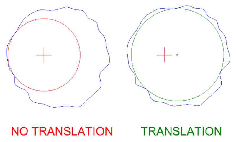
TranslationModifier_kipylw.png


Without the translation modifier, the simulator contacts the datum feature in a way that isn't very good for constraining the clocking rotation.

Evan Janeshewski

Axymetrix Quality Engineering Inc.
 
CheckerHater,
There are two justifications for specifying the translation modifier.
The minor one, in my opinion, is for preventing measurement repeatability issues that may be caused by the very partial contact between the clocking datum feature and simulator. The partial contact may compensate the ability of the datum feature and simulator to apply the rotational constraint. This explanation is also provided in the following Tec-Ease tip, posted by sendithard in the beginning of the related thread:
[sup] May 2010 tip of the month [/sup]

What I consider as the major justification for the use of the translation modifier, is when it better represents the functional constraints acting on the component at its actual working conditions. An example for this is the functional constraints and assembly fits that I described in the post that started this thread. There is no functional support for the requirement of basic location for a datum feature simulator of a press-fit hole, intended for accepting a pin that mates with a slot. A movable datum feature simulator will align the part to the DRF and the tolerance zones in the functionally representative way.

Personally I think that for the vast majority of cases with similar geometries and constraints, the schemes that make sense are either MMB for the clocking datum reference (when the mating component's location in the mechanism is fixed), or RMB with the translation modifier, for press fit, or may be threaded holes used for clocking
 
Status
Not open for further replies.

Part and Inventory Search

Sponsor