Continue to Site

Eng-Tips is the largest engineering community on the Internet

Intelligent Work Forums for Engineering Professionals

  • Congratulations KootK on being selected by the Eng-Tips community for having the most helpful posts in the forums last week. Way to Go!

Hernando de Soto Bridge (I-40 Mephis) 19

Status
Not open for further replies.

human909

Structural
Mar 19, 2018
1,932
Some pretty serious looking issues here.
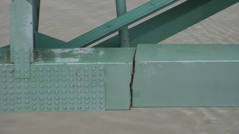
E1NBBdtXsAQ_Xpa_em0owc.jpg

E1NBBduWEAIJnA8_n4vt58.jpg

E1NBBduXsAAqN1p_pg4s4e.jpg
 
Replies continue below

Recommended for you

JohnCE920,

That is the arch tie, and is also a chord of the lateral truss. The force is not there anymore, so the gravity load is being carried by the arch/truss, I suspect mostly by bending of the two span truss, but still partially by overall compression of the arch. As noted before, this structure has exhibited excellent redundancy, as total separation of one vital member has resulted in only minor movement. But it needs at least temporary restoration of the tie before it can be placed back into service.
 
hokie66,

I agree with all you've said. And yes, the redundancy of this structure clearly saved lives this week (or whenever the fracture actually occurred).

I was referring that when the tie fractured and the arch thrust was no longer contained by that member, something had to have taken its place. Maybe the foundations simply 'handled' it. Maybe it went through the deck / lateral bracing system. I do agree there is now no forces in that tie. I get the feeling we're saying the same thing just differently.

My question for the board is HOW do you restore an arch tie? Seems like you'd need to post tension a tie to try and reclaim some of that dead load thrust back into the tie.
 
That is a good question, and I don't know the answer. My inclination would be to live with the displacement, and just restore the member. But the bridge engineers may have different ideas.
 
Does anyone have a clearer image of the bridge drawing? It might show the member forces.

How did they tighten those bolts. Someone had to hold the nut from the inside. I wonder if there is a hand hole anywhere near.

Could there be some torsion in the main tie beam. The main transverse floor beam is suspended by a single rod and pin. When a truck is on the bridge, the floor beam deflects down, which causes the end to rotate. This rotation imparts a torsion into the tie beam.
 
It seems to me that the arch truss would have a significant ability to span on its own as a normal truss (i.e compression in the top chord and tension in the bottom chord), if it needed to once the tension tie is removed.

Although, I'm guessing it wasn't designed that way. I assume the arch action was considered and the overall behavior of the arch truss was that of a single compression arch member with these tension ties at the deck level resisting the thrust. I'd very curious to know how that was analyzed at the time of design 50 years ago.
 
I agree with that assessment abusementpark. That arch looks stout and able to take a lot. But those end piers aren't very stiff in the longitudinal direction (maybe that's a good thing for today). I doubt they were analyzed for taking that thrust and wonder how they're holding up right now.

I'd be curious to know how a bridge like this was analyzed back in the day too. I'd also settle for a set of As-Builts that are scanned in a little crisper than the one sheet the DOT released.
 
Is the subject arch connected to the second arch in a way that it may be proving some counter to the longitudinal thrust?
 
Roy,

It is a two span tied arch bridge, and the trusses forming the arch are integrated at the center support. However, the thrust at the end where the tie is broken is still there. Continuity in the trusses means that the thrust is less than would be the case if these were two simple spans, and that is part of the fortunate redundancy here.
 
Thanks for the explanation. I only recently found this site, and, having more thorough grounding in railroad investigations, this site and its' participants are very much appreciated.
 
Interesting that the crack is two years old, and only recently was it a problem... maybe somebody not doing their job?

Rather than think climate change and the corona virus as science, think of it as the wrath of God. Feel any better?

-Dik
 
There was a crack which got to critical crack length... Its no longer a crack after fast fracture..
 
I don't give that Tweet much credence. To me, it doesn't look like the same place on the bridge, and I can't tell if that line is a crack or not.
 
It certainly seems like the same spot to me. Many details do line up.

(Though I won't bet all my credibility on it as I already feel slightly abashed by not recognising earlier in this thread that this was an tie for the arch.)
 
I see it now, human909. It is on the north (upstream) side of the bridge. I thought it was on the south side.
 
"To demonstrate the power of Flex Tape, I broke this bridge in half!"

Flex_Seal_Bridge_txieur.png
 
CrabbyT-
This is a serious engineering forum.
That was hilarious. [bigsmile]

Brad Waybright

The more you know, the more you know you don't know.
 
Status
Not open for further replies.

Part and Inventory Search

Sponsor