Continue to Site

Eng-Tips is the largest engineering community on the Internet

Intelligent Work Forums for Engineering Professionals

  • Congratulations GregLocock on being selected by the Eng-Tips community for having the most helpful posts in the forums last week. Way to Go!

major Colombia bridge collapses during construction 7

Status
Not open for further replies.

TomBarsh

Structural
Jun 20, 2002
1,003
That's the country of Colombia.

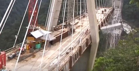
A major bridge, 440 metres span, collapsed during construction. Seems to be a cable-stayed bridge with concrete towers and deck. Seems like one tower and span collapsed during construction, killing at least 10 workers.


A bit more detail and photos showing the scale of the bridge
 
Replies continue below

Recommended for you

It's not easy to see from that video which is though the best seen so far, but it looks to me like the first two cables just to the left as we look at it from the main tower start moving and flexing just before the rest. Would therefore look like the far strut of the V collapsed before anything else di, but it is not easy to see cause as opposed to consequence.

Very sudden catastrophic collapse though. you would have thought something would have started to crack or creak or moan at some point before the initial collapse.

Remember - More details = better answers
Also: If you get a response it's polite to respond to it.
 
I am with LittleInch on this one, my take on the video (@ 0.25 speed on Youtube) is the same as his.

On the 'sudden failure' aspect, would that suggest the furthest fork failed in shear right where the /\ section joins the V of the fork?

That said, it looks as though there is a good amount of dust kicked off the inside of the furthest fork - which I suppose suggest the concrete has essentially 'exploded' under the compression load running around the inside of the fork at bridge deck level. Or perhaps it is the re-bar being ripped out of the concrete?
 
I would expect the deck is being used to hold the legs of the tower together. To me, it appears the deck to tower joint failed on the far side first.

My first though was what an odd way to build a bridge support tower when I saw a picture of the standing structure.
 
Looks to me that the roadbed is sitting on top of a connection between the two legs, although it looks awfully skimpy

bridge_o21wb6.gif


TTFN (ta ta for now)
I can do absolutely anything. I'm an expert! faq731-376 forum1529 Entire Forum list
 
Maybe it wasn't supposed to be sorting on the support but suspended instead? Those cross wire connections in the upper bit of the V above the roadway also look rather weedy.

Remember - More details = better answers
Also: If you get a response it's polite to respond to it.
 
Sure, because that crossmember wouldn't be able to hold the entire load of the bridge; it's purpose in life should only be to support the initial build of the deck, and as additional sections are built up, they're immediately supported by the cables. However, that crossmember is what keeps the legs from buckling out, and would be under tremendous tension, and I would have thought that it would be much thicker, specifically because it's under tension. Nevertheless, in the video, it looks more like the joint between the crossmember and the V-leg is what failed, and there might possibly be a design flaw in that joint.

TTFN (ta ta for now)
I can do absolutely anything. I'm an expert! faq731-376 forum1529 Entire Forum list
 
Counterfeit specifications on the supposedly high strength re-bar?

Bill
--------------------
"Why not the best?"
Jimmy Carter
 
If so, then the other side is suspect too...

Real can of worms here.

Mike McCann, PE, SE (WA)


Well, the towers are absolutely under increasing compression loads from the top down to the V-split. Then, these compression loads are split in two, and become tension loads pulling the two V's further apart. Like two wishbones being pushed down from both ends, the middle of the wishbone is being pulled apart.

So, the weakest concrete and rebar at the top or bottom of the weakest joint of the four will fail first.
 
Did anyone else notice how the deck between the tower and land appears to support itself until the near side tower leg falls onto it? Temporary supports?

Also, was there a crane on the top of the tower? Did they do something wrong with the crane and twist the tower?
 
I'm not sure, but I think there was a tower crane on either end, adjacent to the bridge tower, not on the bridge tower. Google up images, the one on the side that didn't collapse is pretty plain, the other end, I think had one, too, but it's not as clear.
 
If you look at the tower that's still standing, there's a concrete diaphragm wall between the two inclined piers up to the deck level - e.g. see:
This photo also suggests a beam or corbel on top of the diaphragm wall, which looks like it supports the roadway deck. Presumably, one of the functions of the diaphragm wall and / or the top beam is to resist the spreading force of the two piers?

It's hard to see this wall in the collapse video but if you look carefully , you can just about convince yourself that "something" explodes between the legs, and at 0'14", you can see a dark line down the centre of the far pier - is this where the diaphragm wall just pulled away?

Is this a case of inadequate horizontal tension capacity (either by poor design / detailing, or construction defect) of the diaphragm wall between the two inclined piers?

 
Let's just hope that the Colombians are more inclined to share what happened than some of the other South American contries. I don't believe we ever got the story on the overpass which collapsed in Brazil just before the Olympics in 2016.
 
Here are my observations from the posted videos.

There were tower cranes next to each tower. A red one next to the remaining tower and a blue one that is now in the rubble.

It appears to me the initial failure was a tension failure in the diaphragm under the deck that was holding the two V-struts together. The deck is entirely supported by cables so I doubt that thee was any deck loading onto this diaphragm or the beam at the top of the diaphragm.

In one picture there are the tops of what appear to be two towers that are visible behind the mountain in the background. There maybe another similar bridge on the other side of the mountain. Perhaps the $2 billion dollars is the cost of the whole road project and not just this one bridge.
 
Unfortunately I don't think the video actually captures the initial fault. Right at the start of the section with the collapse if you pause and look at the cables closet to the tower they are already not straight and not under tension so it look to me like the tower had already started moving at that point.

I'm struck by a couple of things.

One - how similar is this bridge?
The key difference is that the collapsed bridge is really a tower supported cable stay and is not symmetrical. I can only imagine that once the longer section exceeds the section length attached to the hillside, then as it extends outwards you constantly need to tighten up those three supporting cables anchored to the hillside to prevent any bending of the slim tower structure. I doubt that structure can withstand any bending load but how you accurately monitor the bending is maybe a key issue?

Remember - More details = better answers
Also: If you get a response it's polite to respond to it.
 
Interesting thought LittleInch. The land side of the bridge deck seems to stay in place long after the cables go slack and when the tower is falling the part extending into the air drops with the tower. Maybe the cables were tensioned improperly and bending the tower.

But then, the Mexican bridge isn't symmetrical either. There are supports under the deck on one side of each tower with the deck only hanging from the cables on the other side. I don't believe the cable angle or lengths are symmetric either.
 
There is a cross beam just below the deck. Even if the deck is not fastened to the cross beam, it will be close and the cross beam will support the deck until it all comes unglued.

Bill
--------------------
"Why not the best?"
Jimmy Carter
 
They were putting in a sewer line. Maybe they cut that main tension cross member to get the sewer line in place.
 
Here is some drone footage from August 2017 & a couple of good photos to give a better idea of the Before condition.

Video: Link

Photos:
Link

Link
 
Status
Not open for further replies.

Part and Inventory Search

Sponsor