Continue to Site

Eng-Tips is the largest engineering community on the Internet

Intelligent Work Forums for Engineering Professionals

  • Congratulations GregLocock on being selected by the Eng-Tips community for having the most helpful posts in the forums last week. Way to Go!

major Colombia bridge collapses during construction 7

Status
Not open for further replies.

TomBarsh

Structural
Jun 20, 2002
1,003
That's the country of Colombia.

A major bridge, 440 metres span, collapsed during construction. Seems to be a cable-stayed bridge with concrete towers and deck. Seems like one tower and span collapsed during construction, killing at least 10 workers.


A bit more detail and photos showing the scale of the bridge
 
Replies continue below

Recommended for you

I imagine someone is already comparing details of the Mexican bridge with those of the collapsed Colombian construction. On the video which LittleInch linked, it looks like there are stressbar anchorages on that tension tie, but there is nothing visible externally on the remaining Colombian tower.
 
from looking at the videos there does not appear to be a diaphragm wall below the cross bm on the two main towers while ,at least, one of the smaller towers does show this diaphragm wall.....
 
Bill - not if the crossbeam has broken away from the tower. But then, that "filler" inside the bottom part of the tower below the crossbeam might have stayed in place and been holding everything up.
 
SAIL3,
Look at the photos which epoxybot linked 17:36. There is a wall there. Details unknown.

There are/were only two towers, so am not sure what smaller towers you are talking about.
 
sorry, must have looked at the wrong video...yes there is indeed a diaphragm wall there....
 
That's what I meant, Lionel. You said it better than I did.

Bill
--------------------
"Why not the best?"
Jimmy Carter
 
I think the tower cranes were attached to the flat top of each of the two concrete towers.
 
When you watch the video of the collapse, it appears as though the first thing that happens it the cables on the far side relax and almost simultaneously the lower section of the far side of the tower begins to drop, the web explodes and the bridge deck beyond the tower drops but the bridge deck between the tower & the abutment remains stable until the tower completely fails. So it seems the deck between the tower & the abutment was shored. I wonder if much engineering went into the loads the shoring was placing on the slope above the tower's pile cap?
 
Epoxy bot.

If you look at the photos and videos posted here and others linked when you watch you tube you can see the initial deck was built from both sides to the tower before the tower is completed and appear still be there just before the collapse.

The blue tower Crambe was also attached to the tower by three ties.

Makes you wonder if the installation engineering allowed for all these temporary but constantly changing loads. If some of the deck load was actually taken by the temporary supports and not the cables as the deck extends further out the stresses on the tower would be quite different to its final design load.

Unless there is more footage we can't see I wonder if they will ever really understand what happened.

Remember - More details = better answers
Also: If you get a response it's polite to respond to it.
 
As others have said there was a horizontal 'slab' at the top of the diaphragm wall. However looking at this photo in particular Link, examine the reinforcement in the remains of the wall vs that in the 'tee' at the top of the wall on the right side. Notice what looks like essentially undamaged concrete on the right side as it lies?

This suggests to me the tee might not have been adequately connected to the V columns, also of note is the large amount of reinforcement exposed in the diaphragm wall, but nothing similar visible in the tee (nothing exposed to the same extent at least).

I'd expect quite a lot of reinforcement in the 'tee' if you consider a strut/tie model of what is going on. Distributed wall reinforcement won't achieve the same. Combined with what others are saying it may have simply unzipped at the pier/tee intersection due to insufficient tie reinforcement tying the two sides of the pier together.
 
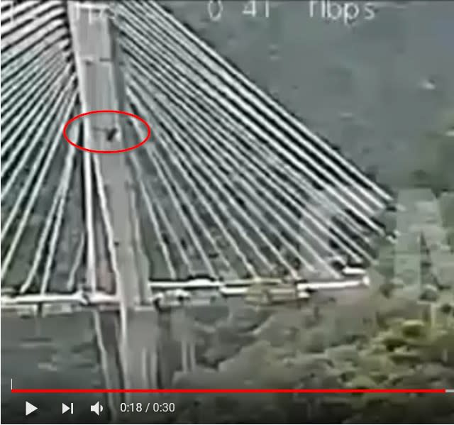
I am far from a structural guy, but slow the youtube down and watch the progression of the area that I have circled. Was that a crack/fracture at the very first frame, or just some weird shadow. It seems to grow to me. You can see it maybe better at the 4 second mark as well.


2018-02-01_17_14_42-20180115_Chirajara_Cable-Stayed_Bridge_Collapse_-_YouTube_buzfi1.jpg
 
Possibly a tower crane brace where the tower crane has been removed?
 
Agent666 said:
This suggests to me the tee might not have been adequately connected to the V columns, also of note is the large amount of reinforcement exposed in the diaphragm wall, but nothing similar visible in the tee (nothing exposed to the same extent at least).

I'd expect quite a lot of reinforcement in the 'tee' if you consider a strut/tie model of what is going on. Distributed wall reinforcement won't achieve the same. Combined with what others are saying it may have simply unzipped at the pier/tee intersection due to insufficient tie reinforcement tying the two sides of the pier together.

I agree with Agent666, and others, who have recognized the perceived 'weak link' in the delta-tower tie element.


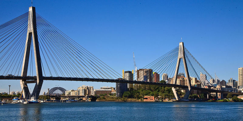
I did a bunch of 'construction' engineering for this bridge back in the early 1990's:

anzac_iler4r.jpg


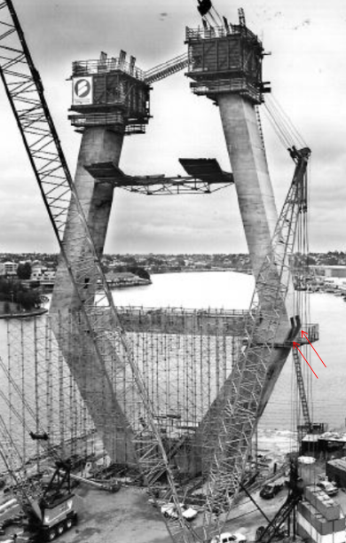
I worked for a consulting engineering company who was engaged by the contractor to provide engineering to numerous aspects of the bridge construction - from delta tower jump forms, approach spans, staged construction analysis etc. The element that tied the sloping legs of the delta-towers (directly below the superstructure deck) was a significantly sized post-pensioned element, with a bunch of PT tendons. The photo below shows the stressing recesses where many PT tendon anchorages were accommodated and later concrete-patched.

anzac_2_ay86ry.png


Delta-towers are very common for cable-stayed bridges. It would be interesting to see the engineering drawings of the tower for this Columbia bridge.
 
Spartan 5 - If you look at the linked photos in epoxybots post of 24 Jan 1735 you'll clearly see the tie struts to the blue tower crane.

The idea or a post tensioned element clearly makes sense and makes you wonder why the web was being constructed in the first place. Most other towers like this don't seem to have it? Was it being used instead of a tensioned element at the bridge deck level?

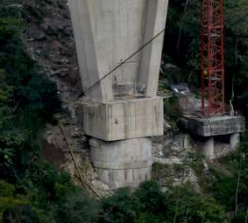
Interesting picture from 3Ddave if you look at the bottom of the concrete. The square base appears to be sitting on a circular shaft type foundation that is smaller than the base?

foundation_ga8oi9.png


Remember - More details = better answers
Also: If you get a response it's polite to respond to it.
 
IRstuff said:
concrete and "tensioned element" cannot be equated.

Sure it can. 'Precompress' the concrete to such a magnitude that, under the applied/sustained tension, there is still a resulting net compressive action.
 
Status
Not open for further replies.

Part and Inventory Search

Sponsor