Continue to Site

Eng-Tips is the largest engineering community on the Internet

Intelligent Work Forums for Engineering Professionals

  • Congratulations GregLocock on being selected by the Eng-Tips community for having the most helpful posts in the forums last week. Way to Go!

Miami Beach, Champlain Towers South apartment building collapse, Part 15 32

Replies continue below

Recommended for you

M11.1 is already awol in the image from all apparent examination (although some seem to question that). So I tend to lean toward the idea that no cars can be seen along the back wall and that any claim of such is spurious. It's just to tempting to imagine what one wants to see. Useless exercise beating a dead horse IMHO. Depending on how you adjust the levels of contrast and brightness you can get to the point where there appears to be a pile of concrete back there and probably just the deck sloping down from back to the wall. I see that in one of Ostroff's videos. 3D depth doesn't help much.

Edit: I will just say I am not certain about anything. If part of a car is actually visible and it could be ascertained that's what it is amidst the concrete I suppose it could have some implications but I just can't imagine it. In the final state after collapse I don't think cars in the garage are visible from above from any photo I have seen (before the controlled demolition). There were cars visible after that so you have to be careful when a photo was taken. This almost seems outside the bounds of reasonable speculation. No shortage of that in the history of this thread.
 
What I don't see is a full thickness of slab laying on the garage floor. That leads me to wonder if the debris in the lane way came from slab collapsing on either side. The slab above the lane way beyond 27 is stiffened by the BMA's on either side and the slab drop half way into the bay. To the east, there is no slab drop and to the west, the slab drop is closer to the building so not as much stiffening. I find it hard to believe that 11.1 is missing and am still expecting it to appear in the shadows. Concrete columns don't seem to have a history of vaporizing, only exhibiting crush but otherwise still standing and in this case punching clean through the slab.

The shiny object is in the USA Today video and is rather nebulous throughout the video. It only vaguely appears in the Tiktok video.

Has anyone been able to synchronize the videos. The amber flashing light reflecting off the ramp wall on the left cycles approx. 12 frames.
 
If M11.1 is in fact laying on the floor in pieces (or vaporized - take your pick), I never really can make this comport with the catenary action that is thought to have detached the slab/deck at the building proper and started the load redistribution. You have to accept the idea that the catenary rupture (for lack of a better term) caused it to disintegrate. And this was the column that seems to have only one rebar sticking out of the floor after the sight was cleared. So maybe M11.1 was just for show by the time this progession began at pace. It would have had to been repaired a lot though over time. And that would have been criminal if that were the case.
 
I would also call it creative to apply band aid repairs that have been documented to have failed. Failed epoxy injection comes to mind. How far did they go?
 
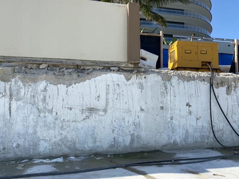
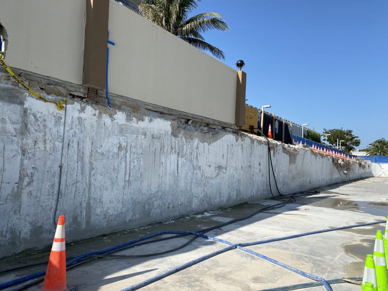
I had posted these photos back in September, these were shot during a walkthrough of the collapse site on 9/10/2021. These show pretty close up if you can zoom on them, look at the damage atop the wall and slab connection.

Also, look where the dark brown stripe on the wall meets the slab, you can see very clear detailed damage and the rebar sticking out.


IMG_0242_cc7qv3.jpg
IMG_0240_ez1qjh.jpg
 
Does the concrete erosion the base of the wall look significantly worse where the generator happens to be sitting? Is water continuing to run in at that spot even after the site was cleaned up?

Well not to say "even after". I think it was a reasonable question to ask how water was entering the basement before the collapse. But I never saw much said about it as they struggled to dewater. Was there a lack of access to observe those details?
 
IanCA (Mechanical) 6 Feb 22 17:53 said:
The linked document is here:
sgw1009 (Computer) 6 Feb 22 18:36 said:
...followed by K12.1...

There are two typos in that document. First the depth of soil I used was 18 inches and not 16 inches. Second, column K-12.1 is actually K-11.1. My apologies.

MaudSTL (Computer) 7 Feb 22 00:50 said:
...there is a gap of about five minutes between the first crash heard on the first floor at 1:10 (which apparently did not cause noticeable debris in the garage) and the deck collapse at ~1:15...

There is a possible explanation that would not cause noticeable debris in the garage. Suppose that column K-13.1 punched through but the deck but was still suspended between gridlines 12.1/11.1 and 14.1 in the N-S axis and between gridlines I and L in the E-W axis sort of like a circus tent that has lost a pole and the tent is still supported by other poles. It is possible that the deflection may have only been of a foot or two. The garage ceiling was about 12 to 14 feet from the video, but I haven't tried to figure it out from the drawings. If the Vazquezes had parked in the northern part of the garage, they might not have noticed that the ceiling was sagging. That might explain the crash at 1:10 AM followed by the complete collapse of the deck at about 1:15 AM. Just a thought.

EDIT: I ran some numbers based on a one-way slab turning into a catenary cable, which is where I came up with the deflection of 2 feet. It should be calculated as a two-way catenary, but I'm not sure I can do that. I decided not to post my calculations so as not to embarass myself, as I am not a structural engineer.

EDIT 2:
Sym P. le (Mechanical) 6 Feb 22 23:21 said:
The lowering of the lobby parking into the garage level may have been graduated by a succession of failures rather than all in one go.
 
Sym P. le (Mechanical) 7 Feb 22 03:43 said:
What I don't see is a full thickness of slab laying on the garage floor.

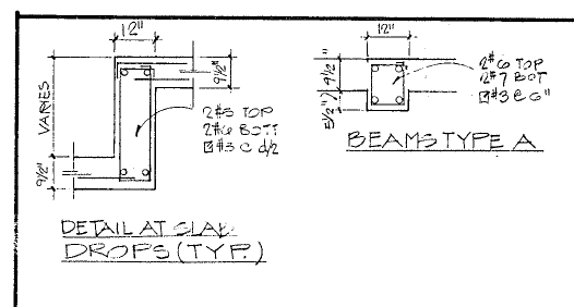
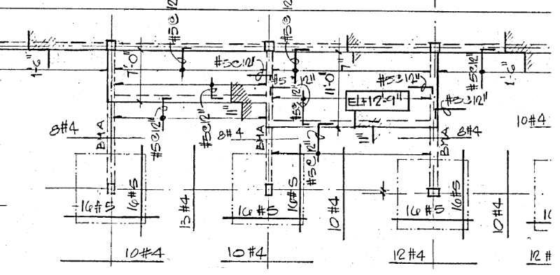
What happened to the structure in front of KLM-9.1 is a head scratcher. Here are some thoughts. The illustrations may not all fit in one comment, so I may have to post them in follow up comments. First of all, here is the detail for the step beam and "Beam A" (see Figure 1).

Figure 1:
Drop_Beam_details_imqtd4_oja75o.png


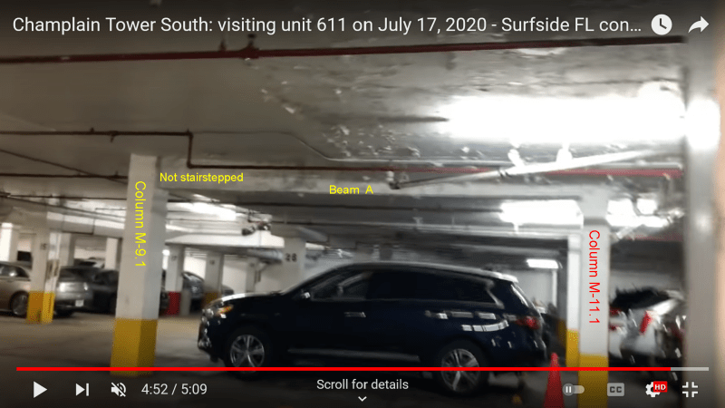
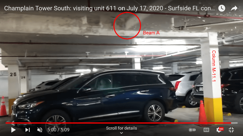
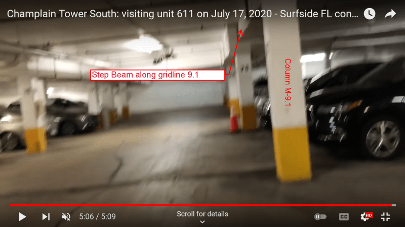
Between K and M along 9.1 the slab drops 7 inches instead of 18 inches. There is a further 11 inch drop between gridline 9.1 and 11.1 between K and M. According to Figure 1, beams type A should have been stair-stepped along KLM between 9.1 and 11.1. However, if you look at Figure 2 (from the garage video), you can see that along M, beam A is NOT stair-stepped. The garage video does not show beam A along K and L very clearly. However, we can surmise that beam A along K was also NOT stair -stepped and that it WAS stair-stepped along L, because the step-beam along gridline 9.1 was shallower between K and M along 9.1. That would have made L-9.1 the weakest column. Apparently not built according to plan. Thus, beam A at column M-9.1 would have had a deeper section that in the drawings and might have been been more resistant to shear. Just a thought.

Figure 2 (three views of column M-9.1):
Beam_A_from_You_Tube_s9byzg.png

Beam_A_from_You_Tube_3_tt17op.png

Beam_A_from_You_Tube_4_nn4y8j.png
 
Here is the detail of the structure in front of KLM-9.1. It is from the original Breiterman drawing s5 of 14 with 1/17/80 revision titled "Lobby Level Framing Plan."
Drop_Beam_detail_along_9.1_between_K_and_M_l1ebns.png
 
Following the creative juices that just flowed, I will throw this imagination in

How does a 2-way slab become a one way slab, resulting in IEGeezer’s 3-ring Circus Big Top scenario?

If his K column punches first, but grid keeps tent ⛺️ up, that stresses all perimeter connections around the failed interior connection.

We definitely have construction joint N-S on East side of drive, and there is probably another one west of K or at K.

So if a big top center pole punches, then the first sides of tent anchors to move are at the construction joints. Thus creating IEGeezer’s centenary one way slab tension between building and retaining wall???

Some rubble falls from initial load transfer, deck sags but remains up for a while, then drops all at once when each end of remaining perimeter anchor points fail.

This would line up with timeline and explain the lateral movements back and forth prior to collapse.

Like a tug of war, if u will. And of course we now have 4 direction wave action between internal center point punch and perimeter sides??? 🤔

If there is N-S construction joint under K line planters, would that not explain failure spreading east and west between parking and pool decks?

Why not keep digging, while neurons are firing? Ventilation fan exhaust in planter along K-Line, probably not well isolated from planter thus any chemicals dumped in that area spread N-S and E-W from that vent location. Thus we have weak concrete and delamination under large loads and skinny columns.

I am leaning IEGeezer Now! However, thst is subject to change just like the wind. The failure could start at wall under planters and spread quickly North down K line.

Ok let me get this off my mind, since Sym P. le reposted death ☠️ by video processing again. I have always wondered why light shining from South-West side of gate, but dark to East side.

Due to catenary action at building, South wall is actually braced better than IJKl column line or close enough they both loose?

Fresh off the press. 💩

EDIT: Zebraso you are up! 😂
 
thermopile said:
I have always wondered why light shining from South-West side of gate, but dark to East side.

Sheet E2 shows all parking level driveway lighting is fed from the emergency panel "XA" and normal power for lights in the parking areas come from panel "HA" . Since the lighting panels are located in the North-West corner of the building and the conduits run in the deck that collapsed, resulting in that debris pile, it could have easily taken out all lights on the parking level East and South of the collapse. Because there are some lights still working I would assume the breakers didn't trip but the conduits or wires were pulled apart.

This space intentionally left blank.
 
NukeDude,

Thanks for your explanation. I was thinking more along the lines of an opening in the deck allowing light in from SW coupled with your explanation. Or a dangling emergency light from wires pulled out of downstream conduit but still on, as per your explanation.

The angle of light bothers me and other properties about it.
 
We had a similar discussion about a stereo pair back in part 7 (search for 'stereo').

@Sym P Le - you have posted a slightly different pair but I still don't see anything convincing apart from the concrete box around where M11.1 should be. You can make your eyes see all sorts of things in grainy images but I don't see a car there. As I said back in part 7, the strange thing about this pic is that you can't see M13.1, which we know survived (it was visible after punching through the deck). That means that the fact you also can't see M11.1 isn't conclusive evidence that that column broke or disintegrated.

However I do agree that it doesn't look like there's a full 9' of slab on the floor there. But if that concrete box is a planter from the deck above, there must be, at least behind it. Perhaps there's just more water in the bottom already than we think.
 
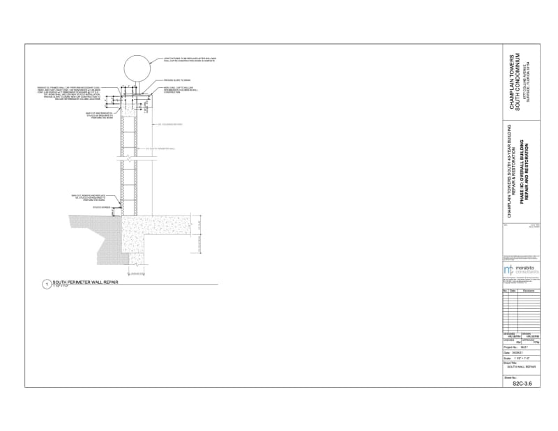
Interesting View of Existing South Perimeter Wall, and what appears to be as-built conditions, contained in the Morabito 40-year certification plans. Note the Deck Slab and a edge beam appear to have been poured on top of wall, thus explaining what looks like a cold joint in the vertical wall.

It appears the capped sheet pile topping was thicker than just the slab thickness.

8777-preliminary-review-plans-for-40-year-re-certification_ywlrkr.jpg
 
Morabito plans were replacing 4 exhaust fans in the garage at existing locations. I have noted those locations on linked plan. I don't see anything in 40-Year certification plans about ventilation fan from pool area that exhausted in planter.
 
 https://files.engineering.com/getfile.aspx?folder=476d6de6-b41c-4ba4-a4eb-146c0314efb5&file=Exhaust_FAns.pdf
thermopile said:
I don't see anything in 40-Year certification plans about ventilation fan from pool area that exhausted in planter.

Someplace I read that one parking level exhaust fan had a missing belt and another had a vibration issue. It's nice that Morabito decided to replace them all. The new pool fan is shown on the drawing that you provided and is labeled EF-P1. It is likely fed from the new "pool equipment room panel" as it only feeds one circuit but it isn't labeled at either end. Morabito's electrical drawings are as bad and incomplete as the original 1980 drawings.

This space intentionally left blank.
 
Nukedude, Thanks again, I see it now. I totally overlooked the new pool equipment room fan and duct work. Working with these images on a laptop computer is not the best scenario... Yes the mechanical report I read mentioned only replacing belts and bearings on exhaust fans.
 
Status
Not open for further replies.

Part and Inventory Search

Sponsor