Eng-Tips is the largest engineering community on the Internet

Intelligent Work Forums for Engineering Professionals

  • Congratulations waross on being selected by the Tek-Tips community for having the most helpful posts in the forums last week. Way to Go!

Miami Pedestrian Bridge, Part IV 74

Status
Not open for further replies.
Peter.

I modified the post upthread to accurately reflect slope.

In any event we have no idea if diagonal #11 had 1% or 3% steel.

And yes about 2000 kips is correct for the equation you used.

But let's talk about AASHTO equations. ø = 0.75, a realistic Aps of 1.75" dia rods & fpu = 150 ksi with a factor of 0.7 to reduce fpu to fpe.

Pr = øPn = ø(0.8(0.85f'c(Ag-As-Aps) + fyAst - Aps(fpe -Epεcu))

=0.75 ( 0.8 (0.85(8.5ksi)(504 - 10(0.6) - 2(2.41)) + 60ksi(10(0.6)) - 2(2.41)(0.7(150ksi)- 28,500ksi(0.003))
=0.75 ( 0.8 (3563 + 360 - 94))
= 2297 kips


I'm still amazed at the seeming lack of mild steel reinforcement at critical shear interfaces such as the anchor blister and now, from this discussion, at the bottom chord as well.
 
Complete newbie here.
Just wanted to point out something I stumbled over. There is a great post from SheerForceEng from 24 Mar 18 01:10. I don't have much to add to it but if I'm not completely mistaken there is a mistake regarding the calculation of the distributed load (Total weight of top+bottom chords).
1.52 x 4.446 x 25 = 168 kN/m should (probably) be replaced by (1.52 m2 + 4.446 m2) x 25 kN/m3 = 149.2 kN/m.

Therefore RA (4236 kN) and also y (8225 kN) and x (7050 kN) are a bit smaller IMO.
 
bobwhite said:
Peter.

I modified the post upthread to accurately reflect slope.
Thanks! I modified my reply to your post too.

bobwhite said:
In any event we have no idea if diagonal #11 had 1% or 3% steel.
I didn't see that value explicitly stated in the engineers' drawings, admittedly.

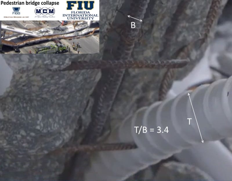
However from the following photographs, I've got something of an idea by estimating that the rebar used is #7, diameter 0.875", area 0.6 square inches.

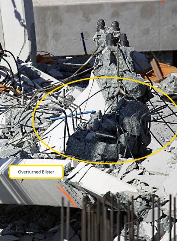
This image tells me that the ratio of the diameter of the rebar "B" to the diameter of the plastic duct "T" is about
T/B =3.4

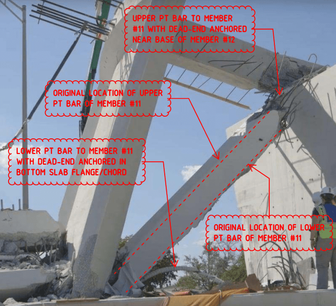
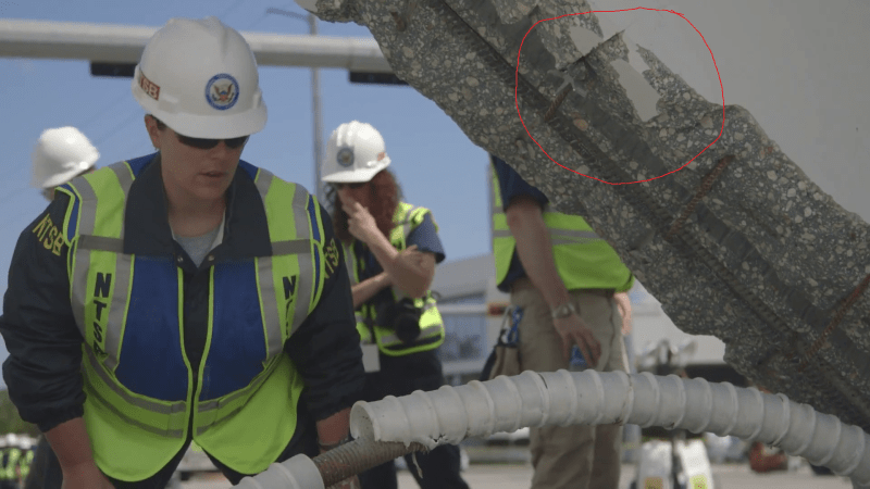
and this image tells me that the ratio of the diameter of the P.T. bar "R" to the diameter of the plastic duct "T" is about
T/R = 1.7
and by substituting for T we can deduce
R/B = 2
meaning that the diameter of the P.T. bar is about twice the diameter of the rebar.

If the diameter of the P.T. bar is 1.75" throughout as per the engineering drawings then the diameter of the rebar is half that or 0.875", number #7 rebar.

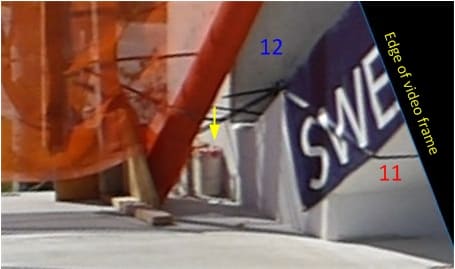
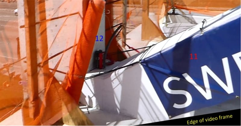
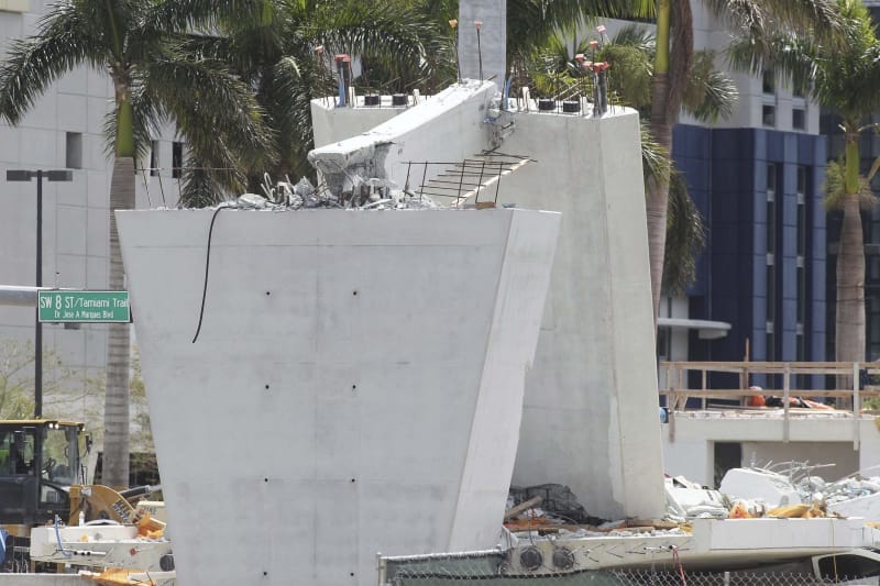
The number of rebars is more difficult to estimate but we can get an idea by looking at this picture which shows the smashed bottom end of member #11 with the exposed ends of the rebars and ties sticking up in the air now -

- by assuming that the ties are #4 (0.5" diameter) bar as per the engineering drawings and trying to count the 0.875" rebars we can see on one side and doubling up to get the total number of rebars, while not miscounting a 0.5" diameter tie as a 0.875" diameter rebar.

Unfortunately, there is not enough resolution in the photograph to be sure of what is a rebar and what is a tie.

What would help would be new high resolution photographs of that exposed end of member #11. If all the bars we can see sticking out are 0.875" diameter rebars then there is maybe more than the 10 I assumed.

bobwhite said:
And yes about 2000 kips is correct for the equation you used.
Thanks again bob.

bobwhite said:
But let's talk about AASHTO equations
Do you have a reference link and page number for those equations?

bobwhite said:
... realistic Aps of 1.75" dia rods ...
... - 2(2.41))..
The P.T. bars are loose in a 3" diameter plastic duct with an area of 7" square inches each. So you have to subtract the area of the ducts from the area of concrete, not just the area of the P.T. bars. That's why I have "-14" in my equation and why you should have "-14" in your equation too.
 
Ingenuity said:
Quote (waross)
I wonder if the upper PT rod in member 11 was removed after it was relieved. Is it visible in any of the pictures?


No, it was not removed.

As per the following photographs of canopy blister and members #11, #12 and bottom chord:
Thank you for taking the time to share this information.
Yours
Bill

Bill
--------------------
"Why not the best?"
Jimmy Carter
 
hydr_engineering said:
Complete newbie here.
Just wanted to point out something I stumbled over. There is a great post from SheerForceEng from 24 Mar 18 01:10. I don't have much to add to it but if I'm not completely mistaken there is a mistake regarding the calculation of the distributed load (Total weight of top+bottom chords).
1.52 x 4.446 x 25 = 168 kN/m should (probably) be replaced by (1.52 m2 + 4.446 m2) x 25 kN/m3 = 149.2 kN/m.

Therefore RA (4236 kN) and also y (8225 kN) and x (7050 kN) are a bit smaller IMO.

Thanks and good pick up.

I have amended it now, and while I was at it amended a couple of other items that have since bothered me:

- Looks like everyone generally agrees that the angle is circa 36 degrees not 30, so I changed this
- I have applied more relevant local load factor of 1.25 instead of 1.2

It still looks like its undercooked but not in such a bad sense as before, this may prove why the bridge stood for a while instead of coming down as soon as they lifted it into place and removed the lifting machine. Definitely on a razors edge in terms of design.

This also agrees with the hypothesis that the system (unknown to everyone at the time) was actually heavily reliant on the temporary PT bars that were "artificially" holding that node together (it looks like at least one of the bars crossed the shear plane that I am speculating upon that is the failure mechanism).

News accounts appear to say that the construction workers were de-stressing these bars when the bridge collapsed so this may have been the tipping point as a result of the design just working/not-working.

If you remove safety factors (on loading and strand capacity) you may actually find that it works (just!!), my computations are still quite under-conservative as well however as it still all comes down to how effective those two PT tendons were in the bottom deck being some distance away from the node itself. Not good detailing imo.
 
Peter Dow said:
Do you have a reference link and page number for those equations?

I recognize that the grout tube diameter was used but in the final condition it would be grouted. Taking that larger diameter into account before grouting is prudent.

Best I have for a reference is other than the original paper AASHTO:


See Caltrans Section 5.6.1

references the equations specifically...

Equation AASHTO 5.7.4.4-3.

Of note I ran a quick calculation on the strut #11 last week with 1% steel using the AASHTO equations and the anomaly is that the phi factor = 0.75 for AASHTO is the same for columns with ties or spirals. I remembered a design force of about 2300 kips.

ACI has a phi factor of 0.65 for tie reinforced columns and a phi factor of 0.75 for spiral reinforced columns.

Between making a mistake with the equation you posted and the fact that I was too lazy to remember that ACI takes a double reduction for tied columns my initial post was inaccurate.

In any event we do not have all of the facts...

ETA: Looking at the photos you used to estimate diameters the items being measured are not at the same distance from the camera therefore the PT duct to rebar diameter is not accurate.
 
By my estimates, the unfactored (external) forces in the members at time of collapse were very roughly:
- diagonal 11 = 1150 kips (comp)
- vertical 12 = 75 kips (comp)
- base slab = 950 kips (tens)

Further, the interface shear demand between the 11/12 joint and the base slab I estimated to be:
- 950 kips (horizontal)
- 780 kips (vertical)

These forces exclude PT forces. Ideally the PT anchorages would be arranged so that PT forces did not contribute to the interface shear demand. Hard to know if this was the case without seeing the details.

The total compression experienced by 11, including PT, I estimate to have been around 1600k while both bars were stressed.

The apparent gap between the bearing pads at the pier means that the entire 950k (H) + 780k (V) force had to be transferred to the base slab by interface shear. It will be interesting to learn of the results of the investigation, and what role the presence of the 4 pipe sleeves along the critical interface played, if any.
 
Peter Dow,

Thanks for your quick assessment which is what I think all experienced engineers should aim at.

Would my interpretation be correct from your calculations that the design axial load of No. 11 is in the order of 2000kips to the ACI standard? Bearing in mind that there is a reduction factor φ so if the actual material were not under strength and dimensions were accurate the actual axial load capacity could be slightly higher.

The failed No. 11 during collapse were carrying approximately half, on account the bridge not symmetrical, of the 950 tons dead weight which is about 1100 Kips / sin 36 degree = 1871kips. .

Thus the No. 11 should not failed by compression because its axial capacity is about twice at the time of collapse . The photos do indicate the body of No. 11 is still intact apart from the bottom PT duct has been ripped out which I suspect to be a consequence of dropping the walkway to the ground thereby pulling the PT duct out of its concrete cover. The breaking of the stirrups might have help the whole face detached. The stirrups clearly were rib open by tensile force.
 
This is #2 during demolition. It is of course deeper in section than the rest.

20180316miami-feluljaro-baleset_xqitjg.jpg


The canopy appears to have been suspended from the top of each upper node.

Canopy_Work_yq1jfh.jpg


Overturned Carcass of a blister.

Overturned_Blister_jxaeef.jpg
 
Is is possible the canopy failed first?
It seems thin, 1/2 thickness of the side view and drawings show six longitudinal tendons near the edges but looks like four were installed.
 
bobwhite said:
Best I have for a reference is other than the original paper AASHTO:


See Caltrans Section 5.6.1

references the equations specifically...

Equation AASHTO 5.7.4.4-3.

Thanks. Here it is.


Calculating the factored axial resistance or factored load should treat the contribution of prestressing steel differently from post-tensioned bars.

It is not appropriate in my opinion to try to apply the term for prestressing steel in AASHTO 5.7.4.4-3 as if that same term could be applied equally to post-tensioned steel.

A prestressed bar which is embedded in the concrete behaves very differently from a post-tensioned bar in a duct. It is not the same calculation, at all.

bobwhite said:
Of note I ran a quick calculation on the strut #11 last week with 1% steel using the AASHTO equations and the anomaly is that the phi factor = 0.75 for AASHTO is the same for columns with ties or spirals. I remembered a design force of about 2300 kips.

ACI has a phi factor of 0.65 for tie reinforced columns and a phi factor of 0.75 for spiral reinforced columns.

Between making a mistake with the equation you posted and the fact that I was too lazy to remember that ACI takes a double reduction for tied columns my initial post was inaccurate.

As specified here, on page 5-4, I presume?


Well I do not wish to venture a strong opinion tonight as to which equation's phi factor is best for tied columns, 0.65 or 0.75, all other things being equal.

bobwhite said:
Looking at the photos you used to estimate diameters the items being measured are not at the same distance from the camera therefore the PT duct to rebar diameter is not accurate.

Well my effort to provide an estimate for the rebar diameter I suggest shows more initiative than simply giving up saying "no idea" and providing no estimate whatsoever.

I would welcome a more accurate estimate - or better still an actual measurement!
 
Looking at the photos of epoxybot and meerkat, it appears there is a blue-green tinge to the concrete. Assuming the colors are relatively close in the photos (the vest is accurate and the Florida State trooper vehicle is accurate), this might imply that GGBFS was used in the concrete mix. Has anyone seen a concrete mix design or any test results of the concrete?
 
Not sure about GGBFS but the original design did claim to use fly ash and silica fume.

"High performance concrete throughout the bridge with fly ash and silica fume admixtures creates a dense low permeable mix design for added strength and durability."
 
saikee119 said:
Peter Dow,

Thanks for your quick assessment which is what I think all experienced engineers should aim at.

Would my interpretation be correct from your calculations that the design axial load of No. 11 is in the order of 2000kips to the ACI standard?

Yes indeed and at the risk of repeating myself here is that calculation again.

Peter Dow said:

Here's a worked example from the same notes, which I have written on top in red ink to calculate the factored load for member #11.


So member #11 is good for a maximum allowable design factored load of only about 2000 kips.

saikee119 said:
Bearing in mind that there is a reduction factor φ so if the actual material were not under strength and dimensions were accurate the actual axial load capacity could be slightly higher.

Nevertheless, the design equations which engineers use employ φ factors for a very good reason.

saikee119 said:
The failed No. 11 during collapse were carrying approximately half, on account the bridge not symmetrical, of the 950 tons dead weight
Mmm.
saikee119 said:
which is about 1100 Kips / sin 36 degree = 1871kips. .

Be careful. Americans use the "short ton" which is equal to 2 kips.
The UK "long ton" is heavier, equal to 2.24 kips.

So the equation for the compressive load on member #11 from half the weight of the bridge is more like

C = 950 kips / sin 36 degrees = 1616 kips

saikee119 said:
Thus the No. 11 should not failed by compression because its axial capacity is about twice at the time of collapse .

The maximum allowable design factored load I calculated, 2006 kips, was nothing like "twice" the unfactored bridge load on member #11 which I calculated, 1615 kips.

If you want to know, the ratio of the two figures I calculated is 2000/1615 = 1.24 - which is not an impressive safety load factor, not when you consider that additional load from post tensioned bars and pedestrians will be adding to the bridge dead load on member #11 and further reducing the safety factor, perhaps to below 1, which is no "safety" factor at all!

saikee119 said:
The photos do indicate the body of No. 11 is still intact apart from the bottom PT duct has been ripped out

Well the top and bottom joint of member #11 look to be destroyed too.

saikee119 said:
which I suspect to be a consequence of dropping the walkway to the ground thereby pulling the PT duct out of its concrete cover. The breaking of the stirrups might have help the whole face detached. The stirrups clearly were rib open by tensile force.

That's one reasonable theory admittedly. There is the other theory that the P.T. bar snapped while being jacked and so it would be very interesting and conclusive to know if the P.T. bar concerned is still intact or not?
 
Apologies if it's outlined above, but can someone tell me the load in #11, and the ultimate capacity of #11?
 
Meekat007,

My theory is No.11 could have suffered a shear failure and moved possibly along the horizontal fillet plane with No.12. There is a short distance for No. 11 to shear horizontally before it hits No. 12 so one member could trigger the collapse, not necessarily two in combination with No. 12. However this theory will require further evidence from the failed point at the deck.
gwfiu_11-12-deck_annot_01_hyd4l2.jpg

gwfiu_11-12-deck_annot_02_jolrwr.jpg

The inline angle flattened resulting even higher compression inside No.11 while partially broken and sheared interface could start disintegrating under the high compression.

No. 11 could not remain static but slide toward the north eventually bear against No. 12 which was not strong enough to restrain NO. 11 or stop the failure. It had even less shearing resistance weakened by 4 plastic pipes plus some embedded items cast around its perimeter.

Once No. 12 and 11 moved or broken away from the deck the truss system would act as through No. 11 was missing. This put the loading duty entirely onto the walkway deck to resist the dead load by bending which is of course inadequate and has not been designed for. Thus the deck failed and folded.

I believe it was the folding of the walkway deck that pulled the bridge off the pier or abutment. With No. 12 previously pushed out and resting on the top of the pier No. 11 rotated with its bottom now at the top. The bottom PT tendon appeared to have been firmly cast into the walkway deck which dropped onto the ground. Does bottom PT rod have the ability to stay inside the truss member? It is embedded in concrete and confined inside stirrups. Can it keep the dropping deck from falling?

In the end 1/5 of the bridge 950 tons pulling the 1.75" (45mm dia) high yield PT rod out of No. 11 and broke every one of its either 3/8" (10mm) or 1/2" (12mm) diameter stirrups(my estimation). Some photos showed the stirrups were bent about 30 degree after breaking. This makes me think the surface layer of concrete had to come out first before the stirrups could be cut and bent this way. Since the concrete did not spalled after the corner of the stirrups so I assume only the surface layer debonded according to the photo.

miami_memner_11_pt_bars_oroq6v.png

member11_closeup_ogp8at.jpg


lucky555

No. 12 and it connecting canopy in my view are not major structural elements and can be omitted in the analysis. Their presence may add a few percentage points accuracy to the calculations like adding rotational resistances. The No. 12 is there to carry the dead weight of the first bay. The first bay canopy provides anchorages for the PT system. The second bay canopy carried major compression and would have crumbled if failed. In the end it folded just like the walkway deck.

The connection of 12 with canopy has only air to restrain any longitudinal force and can move bodily. It remains in a surprisingly good condition after the bridge failed.
AR-303209450_heuw30.jpg
 
Status
Not open for further replies.
Back
Top