Continue to Site

Eng-Tips is the largest engineering community on the Internet

Intelligent Work Forums for Engineering Professionals

  • Congratulations KootK on being selected by the Eng-Tips community for having the most helpful posts in the forums last week. Way to Go!

Miami Pedestrian Bridge, Part IX 33

Status
Not open for further replies.

JAE

Structural
Jun 27, 2000
15,444
A continuation of our discussion of this failure. Best to read the other threads first to avoid rehashing things already discussed.

Part I
thread815-436595

Part II
thread815-436699

Part III
thread815-436802

Part IV
thread815-436924

Part V
thread815-437029

Part VI
thread815-438451

Part VII
thread815-438966

Part VIII
thread815-440072


Check out Eng-Tips Forum's Policies here:
faq731-376
 
Replies continue below

Recommended for you

Vance Wiley, thanks for your correction.

From FIGG's presentation, on page 1:

On 03/13/18, MCM e-mailed FIGG documentation regarding the cracks and FIGG
instructed MCM to install the recommended temporary shims in the pylon base directly
below member 12 (nodal area of members 11/12) between the permanent support
shims

from the slide on page 6:

Tuesday morning, upon seeing MCM'S information, FIGG requested that, as a prudent action MCM immediately install temporary shims directly below the nodal area of members 11/12 and the top of the Pylon/Pier, while further evaluations were on-going by FIGG.


Is there any indication that this was completed or were they still working up to it? Did they lift the span and reset it or just jam stuff in there? Did the remedial action relieve any relevant distress to the structure? Also, the presentation appears oblivious to the significant cut-outs. It just adds to the high drama of incompetence.
 
jrs_87 said:
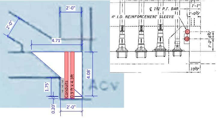
Note what appear to be four through holes for the 190 foot pylon.
Sym P. le said:
Instead the forces had to be carried through the slab, around those four holes to the laterally placed shims.

Regarding the four holes, and in connection with the Mar 15 "cracks" meeting and PowerPoint presentation. You might look back to May 11th on the current page of this thread, where this was discussed:

gw-shear-plane-02_l9insk.jpg


Basically the PowerPoint calculation of shear looked at the vertical planes on each side of the projection of #11 through the deck and diaphragm (not the horizontal plane between #11 and deck), and failed to take into account the four holes. So that area was overstated by 50% (ie: should be reduced by 33%). That was one of three aspects of the presentation's calculation that appears to overstate the shear handling capability of these planes.
 
TheGreenLama said:
here's a member load summary extracted from the LARSA model

Thanks for posting those diagrams, which add significant understanding of the otherwise somewhat cryptic pages of tables in the calcs.

Do you have further insight into the meaning of the multiple columns (P/A@Centroid, And Normal Stress at points 1..4), and also the multiple rows per Member (Stations 0..2)?
 
Re: Sym P. le (Mechanical)5 Jun 19 21:20

Your mention of slides reminds me pdf states "first few slides were not photographed", so are missing from us.

As for the emergency shims, timelapse video covers that time frame. 16GB

While not conclusive, I see no sign in video emergency shims were actually installed.
 
gwideman - I think you called it here - you posted "Basically the PowerPoint calculation of shear looked at the vertical planes on each side of the projection of #11 through the deck and diaphragm (not the horizontal plane between #11 and deck)".
From what I recall, a recent post (yours, I think) had a shear plane at the top of the deck until it intercepted the sloping plane of the PT rods and followed down at the PT slope, where it exited the end of the deck. I think that will be found to be the failure plane. It also explains the cracks in the top of the deck, which FIGG could not explain in pages 39,40,and 41 of their PP show. As the shear plane followed the PT slope it went deeper into the top of the deck, causing the cracks at the surface and rupture from the end of the deck.
 
VW - if the failure was in the bulk of the deck then that chunk of deck would have remained attached to 11/12. Instead the deck was sufficiently strong as to pull the lower PT bar out of 11. The failure plane is the cold joint between 11/12 and the top surface of the deck.
 
output_jgl1jf.jpg


Gwideman, I'm no expert in LARSA, but this is how I interpret the output format. Each "beam" member input into the computer model goes between defined nodes. Station 0 would refer to the first node, station 2 refers to the end node, and station 1 is the midpoint.

For stresses you're following the basic formula (for 2D behavior):
normal stress = (P/A) +/- (Mc/I)
where P is axial force, A is area, M is moment, c is distance away from centroid to stress point, and I is the moment of inertia.

The "points" are then locations on the cross section where a stress is calculated. These points are defined in the input somewhere. For the rectangular diagonal members I believe they've been defined as the four corner points, beginning in the upper right corner, then going around clockwise. For the deck, where 6 points are defined (I believe 6 is the max allowable for LARSA), I'm not exactly sure. But they'll be extreme points on the cross section, and will move clockwise around the perimeter.

In our situation, where we only have bending in one direction, half the points are redundant. So, from this stress table you should be able to back out axial and moment forces.
 
3DDave - I agree the the failure likely began at the cold joint - and days before the collapse. But it appears that, on the way, something developed enough resistance to the movements to transfer enough loads to the top portion of the deck, and cause the cracking photographed on March 13, at the west side of the node and the beginning of the blowout in the end of the deck.
Thanks for your comment.
 
I uploaded an edited version of one of the FIU timelapse movies that is only concerned with the bridge install: YouTube video - details are in the video comments area - video was cropped, enlarged and slowed down. The video is unlisted so it won't show up in any Google search, but the link can be shared.

Highlights: Lots of manlift activity at the north end, the northeast (video front-left) corner of the span appears to make contact well before the northwest (video front-right) corner is set down, and at one point the north end was rapidly lowered - or dropped??
 
MikeW7 (Electrical)7 Jun 19 00:3

Mike, good observation.

I zoomed in some more. The northeast extreme corner of diaphragm rotated down and if it did not make concrete to concrete contact at pier surface, it at least went lower than shim top level. After that the corner had to raised back up to level diaphragm and clear shims. This video will fuel previous suspicion that span was rocked into place. Edit: Unfortunately, as I re watch video in loop, I see slightly different dynamics, so I'm not sure what I'm seeing. Also, trying not to blink puts me in trance.

 
MikeW7 said:
edited version of one of the FIU timelapse movies [...] slowed down

This is interesting for a variety of reasons. It really amplifies a defect that I now see is in the original videos: the frames are not uniformly spaced in time. All the downloaded videos (600x, 48000x, 1000000x) have this same issue. For example, in the 600x, which should provide the finest time granularity, they proceed frame, frame, frame, jump, frame, frame, frame, jump...

This suggests that in the original source video there's at least one more frame that was dropped, probably in order to result in a particular average frame rate.

Looking at video Bridge-109 Mar 8-19 2018 600X-1080.mp4, at the 14:41..42 range, it looks to me like the frame at which the bridge is first seen collapsed is right after such a jump. Which would mean there is a frame missing right before that (which could be just before collapse, just after, or during). That might be a very interesting frame.

 
qwideman - Yeah, the framerate on all the videos is dynamic. Something like a quick 3-shot burst then a long (5-10 second) delay. I initially thought a section of north video you mentioned had been edited out right before the bridge collapse (because of the way the lightpole shadows jumped like the second-hand on an analog clock) but finally decided the jerky gap was typical of the rest of the video.

I also examined the videos from the southwest and southeast cameras but there didn't appear to be any unusual movement when the span was seated.

One other oddity is that when the span was first lifted in the predawn (viewed from southwest) the span noticeably rocked side-to-side.

So much for insuring the span never exceeded 1/2 degree of flex/twist at any time. I wonder if the "computer shutdown" that caused the data loss was more than an accident...

One more reminder about Kevin Hanson - I'm sure he was present when the ends were tensioned before the move, and he was well aware of what the initial hairline cracks looked like. Immedediately after the span was seated (not sure if ends had been de-tensioned yet) he observed gaping cracks, took pictures (still unreleased) and forwarded them to his boss. It wan't until 3 days later that the other set of pictures (now publically released) were taken. The hairline cracks were indicative of an underlying defect, but the process of moving and seating the span is apparently what damaged it.
 
I created a couple of more videos from the north-view timelapse - one for the collapse day morning inspection crowd, and another for the bridge collapse starting when the mobile crane is fired up. All three videos are collected in a YouTube playlist. The videos and the playlist are all unlisted - the links can be shared, but they will not appear in a Google search.

EDIT - video comments are also disabled to limit my liability.
 
MikeW7 said:
One other oddity is that when the span was first lifted in the predawn (viewed from southwest) the span noticeably rocked side-to-side.
If you haven't seen it yet, there was an on-board video of the move, with the camera on the north end. This clearly shows the north end (at least, maybe it was the entire span) rocking from side to side, starting around 0.45 into the video. Link

And is there any chance a settling substructure could be one of the contributing factors? There is a lot of dredging being done in the canal before the collapse next to the newly-installed canal bulkhead on the south side of the canal. This was intended to support fill for the pylon (and the north end of the span), but I have yet to see any plans that show this bulkhead, as opposed to the bulkhead on the north side of the canal (for the adjacent span). The south side bulkhead was only needed once the bridge was shifted 11 feet north to accommodate a future road lane. Did they just duplicate the other bulkhead without any geotech studies or additional engineering? Also note that on the plans which can be found here Link, the canal bulkhead was designed to be only about as deep as the proposed bottom of the canal after dredging. Does this seem deep enough to protect the driven piles and thus support bridge piers?
 
Wetlander (Specifier/Regulator)7 Jun 19 12:11

The rocking is more apparent if you restrict your view to the distant horizon. The hydraulic lift system was not capable of lifting all rams simultaneously. Rocking is result of alternating pressure.

Please note in video what appears to be a cardboard box of thin stainless steel shims on top of pier.

ssshims_ryuiqi.jpg
 
I'll upload a bunch of videos tonight to a dedicated YouTube channel (unlisted). It will contain segments from the north and soutwest FIU timelapse videos, and a southeast timelapse by Peter Grant. As soon as the new channel is up I'll delete the old videos & playlist.
 
Status
Not open for further replies.

Part and Inventory Search

Sponsor