Continue to Site

Eng-Tips is the largest engineering community on the Internet

Intelligent Work Forums for Engineering Professionals

  • Congratulations KootK on being selected by the Eng-Tips community for having the most helpful posts in the forums last week. Way to Go!

Miami Pedestrian Bridge, Part XII 34

Status
Not open for further replies.

zeusfaber

Military
May 26, 2003
2,466
A continuation of our discussion of this failure. Best to read the other threads first to avoid rehashing things already discussed.

Part I
thread815-436595: Miami Pedestrian Bridge, Part I

Part II
thread815-436699: Miami Pedestrian Bridge, Part II

Part III
thread815-436802: Miami Pedestrian Bridge, Part III

Part IV
thread815-436924: Miami Pedestrian Bridge, Part IV

Part V
thread815-437029: Miami Pedestrian Bridge, Part V

Part VI
thread815-438451: Miami Pedestrian Bridge, Part VI

Part VII
thread815-438966: Miami Pedestrian Bridge, Part VII

Part VIII
thread815-440072: Miami Pedestrian Bridge, Part VIII

Part IX
thread815-451175: Miami Pedestrian Bridge, Part IX

Part X
thread815-454618: Miami Pedestrian Bridge, Part X

Part XI
thread815-454998: Miami Pedestrian Bridge, Part XI

Check out Eng-Tips Forum's Policies here:
FAQ731-376: Eng-Tips.com Forum Policies
 
Replies continue below

Recommended for you

RAB 678 said:
Yes and like I said lets backtrack and analyze these statements...........
(my responses will be in parenthesis)

Obviously the designers made very significant errors and that lead to the collapse. These failure mechanisms were understood for decades now and the appropriate design checks are in the concrete codes. It was a serious oversight in the design and there were mistakes the contractor and engineers made when the cracks appeared. However, the fundamentals are that the bridge could have been designed properly as a concrete truss.

I could spend hours on each item you bring up but the best thing to do is a proper analysis and all the required design checks along with a full independent review. There are aspects to the design that would have to change (obviously) but it is feasible and in rare circumstances could make some sense. I doubt now that any one will be jumping in line to design a concrete truss bridge.

Don't forget that there have been many other bridges with other materials that have failed suddenly but that doesn't stop us from having bridges.
 
MikeW7 (Electrical) said:
The upper part of the cloud is also visible in frame 73
I notice that also. EDIT I also note a white stripe to the left of the black lower arm of the cherry picker that continues through most of the video
 
SFCharlie (Computer) 14 Jul 19 14:41 said:
I also note a white stripe to the left of the black lower arm of the cherry picker

The photo posted by Tomfh (Structural) 11 Jul 19 11:52 doesn't show anything on the north side of the lift arm, but other chopper pics pics show a white stripe on the north side of the arm, but this wouldn't be visible from the truck dash cam.

EDIT: no stripes on either side:
 
In saikee119 (Structural)8 Jul 19 16:38 post, it is visible in frames 76, 77 EDIT 78, 79 also. Gone in 80.
I did not intend to imply it was real...
 
My guess is that it's a specular highlight (reflected sunlight) on the nearly upright bottom arm from the nearly noon sun. Just one more spooky coincidental alignment to mess with our eyes.
 
Concrete under long term compression does creep, resulting in changes in member lengths.
One of the benefits (?) of prestressing concrete is the ability to "tune" the structure, much like a piano or guitar. Like a stringed instrument, talent is required in that tuning.
This structure had PT forces in both the deck and canopy. Tuning these forces to produce higher compressive stresses in the deck than in the canopy under self weight conditions can actually result in upward camber over the long run. Adding live loads would cause elastic reactions which vary with load intensity and likely exist over short periods. Predicting the effect of the "open web" conditions which must transfer the horizontal shears between the canopy and deck is much more difficult.

Overall, with both the canopy and deck being under compression basically all the time, the structure will shorten. The immediate shortening of the deck under the PT forces is about 5/8 inch, if I did it right.
It might shorten another inch over its expected service life. That is a guess, without any calc. Thermal expansion is within the elastic range and will basically increase the compression a bit or reduce it a bit, with basically elastic reactions in the concrete. Because the PT strands are well within their elastic range, they will respond accordingly, and basically be a constant force applied at the ends of the deck and canopy, maintaining compression in the concrete and preventing and cracking from tension stresses.
To insert a 'pun' here, the 'key' is in the tuning.
Because the canopy has a greater surface to mass ratio than the deck, I would expect the canopy to react a bit faster to changes in solar exposure and air temperatures. This could cause some different expansions in the canopy compared to the deck, and initiate some rise and fall cycles on a daily basis. I will let the Mechanicals advise on this effect. If the result is significant movements, the cycling strains on web members could cause cracking and a cause for concern,

Your comment "it hangs from the canopy)" is perhaps a bit too limiting. The canopy is in effect the top chord of the truss, and provides the added benefit of some shading. The deck is the bottom chord of the truss, with the added benefit of being the walk surface supporting people. And the webs connect those elements, creating a "truss". In effect, the structure depends on each and all of these pieces doing their job, and therefore "hangs" on each and every one of those components. Thus the concern for a lack of redundancy.
Thank you for your comments.


Earth314159 said:
Even though the deck has a net tension, the concrete is in compression (at service load levels).

Hi Earth 314159 -- Your statement above is 100% incorrect and wrong. In the vicinity of the connection between deck and node 11/12 the concrete in the deck is under a fantastic amount of tension under all load conditions.

This is because the deck in that vicinity is under fantastic shear load, and as we know (see, Mohr's circle), shear is a combination of compression in one direction and tension in the orthogonal direction. It is that tension that killed off this bridge, and the six human beings underneath it. There was no steel in place to take that tension.
 
Fortyyears experience said:
Hi Earth 314159 -- Your statement above is 100% incorrect and wrong. In the vicinity of the connection between deck and node 11/12 the concrete in the deck is under a fantastic amount of tension under all load conditions.

This is because the deck in that vicinity is under fantastic shear load, and as we know (see, Mohr's circle), shear is a combination of compression in one direction and tension in the orthogonal direction. It is that tension that killed off this bridge, and the six human beings underneath it. There was no steel in place to take that tension.

I am talking about the deck as a whole and not the disturbed region at the joint. I have written multiple times about the shear/tension etc. at the joint and I am well aware of it. I have also done the calculations for myself.

If we could take the comment "the prestressed concrete is all under compression" literally and without exception, we could build out of sand rather than concrete. You have to put the comment in context.

BTW, Concrete in shear is not necessarily accompanied by tension stress. You can have shear with 0 tension or even two different compression stresses from orthogonal directions. The mohr circle is simply shifted to the right.
 
Earth said:
BTW, Concrete in shear is not necessarily accompanied by tension stress.

Not necessarily, but almost always. And it's not really true to sat the shear is "accompanied" by tension. The tension is part of the shear.
 
Tomfh said:
Not necessarily, but almost always. And it's not really true to sat the shear is "accompanied" by tension. The tension is part of the shear.

The tension is the components of the shear stress and vice versa. It is just a matter of perspective. I get that and that is part of my point. I am not too sure exactly what wording you would like me to use. I really didn't want to be pedantic about it. The mohr circle is just derived from the statics of a stress tensor at a point.

In concrete, the principal stresses at 45 degrees are commonly not in tension. If you have a crack at 45 degrees in the web, as soon as the concrete cracks, the mohr circle taken at the edge of the crack shifts to the right and will have zero tension (it has too since tension cannot cross a crack)in the principal direction. This is where compression field theory comes from. If the mohr circle is taken right at a tie/stirrup location, the stresses change again. Having a mohr circle with equal magnitude principal tension and compression (a circle with centre at the origin (x,y)=(0,0)) is not the common condition. The mohr circle varies from point to point.
 
[highlight #FCE94F]ADD: The vertical movements and distortions shown in the frame images and GIFs are real, but they are probably enhanced to an unknown degree by the 1600% enlargement process. Just because something seems to move 6" (even in the raw pixel data) doesn't mean it actually moved that much. The important thing to glean from this data is that observable movement occured, but it's magnitude is unclear.[/highlight]

Been working on this for two days. I'm tired. There are probably still a few typos....

THE SMOKING GUN

North_View_Smoking_Gun_oq3ase.gif


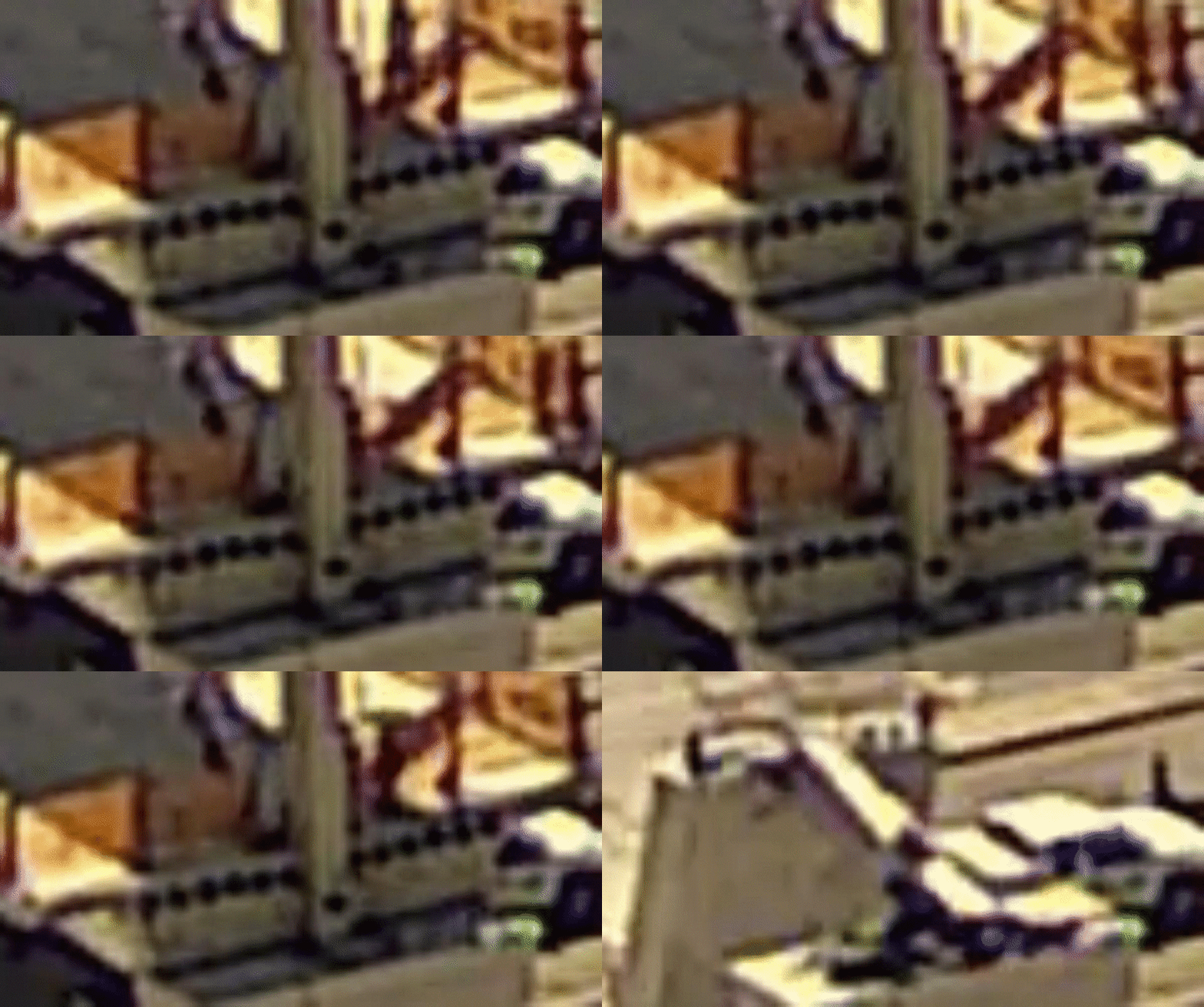
So ........ I found a "smoking gun" late Saturday night, hidden in plain sight and already viewed countless times. I spent the last two days figuring out details and writing this post. It turns out a small cluster of pixels can tell quite a story if the right questions are asked...

The GIF above shows the last 20 frames of the North View timelapse, zoomed in by 16x. The order of events are as follows:
[ol 1]
[li]Kevin Hanson is standing in shadow to the right of member 12, looking at the 11-12-deck joint.[/li]
[li]Hanson moves to the NW deck corner (possibly to talk by phone with his canopy crew).[/li]
[li]Hanson moves in for a close up view, then returns to the NW corner.[/li]
[li]Just as he leaves, member 12 starts moving up and down and the diaphragm to its west lifts upward - watch the area to the right of the 8" drain.[/li]
[li]A short pause is followed by the collapse of the bridge.[/li]
[/ol]

The GIF was made from individual JPEG frames using the GIF Maker at
It turns out a large section of the North View timelapse, about 170 frames to be exact, documents Hanson's movements as his tensioning crew works on the canopy, and the warping of the 11-12-deck joint that resulted from their actions. Most of these structural movements are much more subtle than the coup de grace that finished the bridge, but they seem to follow a predictable pattern of adjust and wait.

HISTORY

This all started with the Saturday discussion about a dust cloud that was observed (in the truck dash cam video) at the north end just before the bridge collapsed. I began with the North View timelapse source video and zoomed in by a factor of 8x, then 16x, to observe the north end itself, and what went on as Kevin Hanson was actively checking the cracked areas while his tensioning crew was making adjustments on the canopy.

What I saw was unexpected and remarkable. The bridge collapse was not an instantaneous event. The 11-12-deck joint and surrounding area was experiencing repeated cycles of distortion and relaxation as Hanson's crew worked above. I spent most of Sunday experimenting with deciding how much enlargement to use, what type of interpolation to apply, whether other filters might show clearer results, and documenting when critical events occured. Today I worked on this writeup, which took a lot longer than expected.

METHODOLOGY

Editing tools: Open source video editor VirtualDub2 and freeware file viewer IrfanView

I started with the 1920x1280 North View timelapse (Bridge-109 Mar 8-19 2018 600X-1080.mp4) and used VD2 to crop out a work area that included both corners of the deck, the top of the north pier, and enough of the deck area to locate Kevin Hanson as he paces from NE to NW deck corners. I settled on a 120x67 crop that enlarges to 1920x1072 at 1600% magnification, which is almost identical to the standard 1080p video size. This enlargement is big enough that everyone should be able to see exactly what I produced without the addition of artifacts created by their viewer's interpolation routine.

For the time span, I decided to start at the point where Hanson ends a face-to-face conversation with a mystery person. After this meeting he appears to be solely devoted to checking the 11-12-deck joint, and making periodic phone calls to his canopy crew. This start time corresponds to 1:59 in the Collapse - N View YouTube video, and Frame 26252 (14:35.942) of the source timelapse video. I stopped at source Frame 26425, a couple frames after the bridge collapsed.

In the past I've enlarged using the "nearest neighbor" interpolation because it retains the original blocky nature of the source video so details are preserved and artifacts are avoided. It works by replacing each original pixel with a block of identical pixels - for 400% enlargement, each pixel is replaced by a 4x4 block.

For this project I wanted to enlarge by a much larger factor, and I wasn't concerned with preserving detail because there really wasn't any because the area was so small, so I used bilinear interpolation, a method that spreads each 2x2 block of source pixels apart then uses simple linear interpolation (in 2-dimensions) to calculate intermediate pixel values, in this case 252 "new" pixels to completely fill a 16x16 grid. There are several variations of this algorithm, but what I used is the Precise Bilinear interpolation method that's a native feature of the VirtualDub2 filter kit.

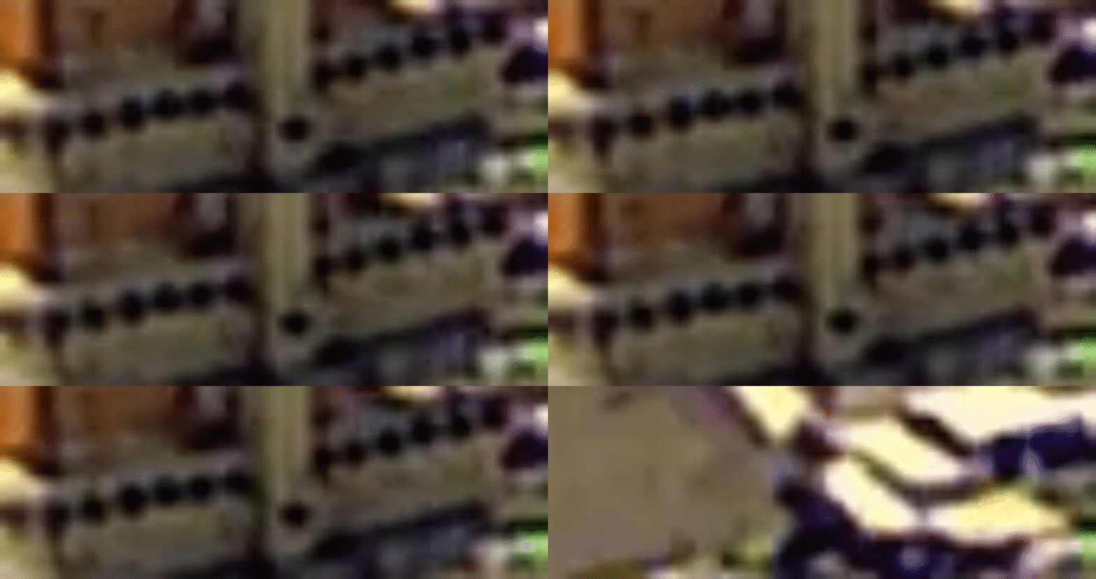
A comparison of Nearest Neighbor (NN) and Precise Bilinear (PB) for a 120x67 crop are shown below:

16x enlargement of cropped Frame 26293 using Nearest Neighbor (NN):
NN_at_16x_-_Frame26293_aqkfys.jpg


16x enlargement of cropped Frame 26293 using Precise Bilinear (PB):
PB_at_16x_-_Frame26293_njkwal.jpg

As you can see, PB is useful to "guesstimate" the shapes hidden within blocky pixels, and at 16x it was very effective at magically converting square pixels into believable representations of the 8" drain pipe and tendon sleeve openings in the north end of the deck, as well as the proper shapes of member 12 and Kevin Hanson.

Much more important, however, is the fact that PB can detect subtle motion. As a sharp feature moves within the area covered by two source pixels, the pixel colors change value to provide an indication of the changed location. If 2x interpolation is used, movement can be detected at approximately 0.5 pixel resolution. 4x interpolation yields 0.25 pixel resolution, and so on. Motion detection at 16x is down to 6% of a pixel width, which means very subtle motions can be detected, like the displacement of member 12 and diaphragm warping.

ZIP FILES

For the image analysts, here's a 16MB ZIP file that contains:
[ul]
[li]A folder containing all the images for the period when I believe the tensioning was occuring, frames 26252 through 26425 of the North View timelapse video (174 frames) saved as JPEGS with 80% compression.[/li]
[li]A bonus folder containing the NN versus PB comparison images.[/li]
[/ul]

[highlight #E9B96E]ADDS:[/highlight]
[ol 1]
[li]If you decide to analyze the "smooth" Precise Bilinear (PB) interpolated images, be sure to have a look at the "chunky style" Nearest Neighbor (NN) versions before you make any decisions about the reality of what you think you see. Here's a ZIP file of the same 174 images as above, at the same 16x enlargement, using Nearest Neighbor interpolation.[/li]
[li]Here's another ZIP file containing 100 control frames (21960 to 22060) from the previous day, taken at the same time, so you can understand what the undisturbed North View looks like. There's a lot of wind buffeting, but the spatial relationship between all components remains very stable, an indication that the distortions seen on the collapse day were, in fact, distortions. NOTE: I forgot to put them is a folder before they were zipped.[/li]
[li]ZIP file of last 44 frames of North View closeup, cropped to include the entire north end (canopy, member 11, deck, and pier top). This time I remembered to put them in a folder.[/li]
[/ol]


ANALYSIS NOTES

The frame rate is not constant. It appears that an intervalometer was used to make the camera shoot a short burst of three frames followed by a multi-second time delay. A good estimate of the frame intervals can be found by observing traffic movement in the source video, and noting that a car moving at 30mph is moving at 44 feet per second, but that's a project for another day....

High power enlargement is hampered by many factors:
[ul]
[li]The change in one source pixel value affects the interpolated values of a surrounding 32x32 block of calculated pixels.[/li]
[li]Motion artifacts can be caused by camera shake (wind gusts, nearby auto and foot traffic, birds, etc.)[/li]
[li]The absolute location of the image sensor can shift by several pixels due to thermal expansion of the camera body, it's mount, and the structure the mount sits on.[/li]
[li]Sun motion alters indirect illumination, shadows and reflections.[/li]
[li]Imaging sharpness can be diffused by dust kicked up by nearby construction activity.[/li]
[li]ADD: As discussed below in my posts of, 16 Jul 19 15:38 and 16 Jul 19 16:39, objects that extend toward the camera, or edge surfaces that are viewed from the side, may appear to be flattened and have no 3-dimensionality if they are represented by a small number of pixels.[/li]
[/ul]
Making determinations required a disciplined plan:
[ul]
[li]Since the tensioning process was performed in steps, I looked at surrounding frames to insure the motion I observed was confined to a small number of frames, surrounded by a larger number of more stable frames.[/li]
[li]Then I quick-stepped back and forth between frames (using IrfanView) to ensure that only a specific area was showing movement.[/li]
[/ul]

I discovered the GIF Maker tool just recently, but I think it would make a useful tool to make permanent loops of frames that contain suspected motion, allowing you to just sit and stare at all parts of the image before making a decision. The GIF frame rate is also adjustable as a percentage of 1.00 second.

ADD: As an example, here's a GIF made from 85x30 crops (enlarged to 1360x480) of the last 7 frames, with 1 second between frames:
North_View_Smoking_Pistol_eld1kn.gif


FRAME-BY-FRAME COMMENTS

The frame sequence begins with the departure of a mystery person who was talking with Hanson. After that person leaves, Hanson actively begins checking the cracked area at the 11-12 node, walking from one side of 11 to the other, and at times just crawling over 11. He stops often in the NE or NW corner where he appears to be having conversations with his work crew using a phone, since his arm is held up to the side of his head instead of his mouth as would be the case with a walkie-talkie. In one or two cases there appeared to be lengthy conversations, possibly with an outsider. (Any guesses??)

Here are my notes on what I THOUGHT I saw, using the last 3 digits of the frame number. Your opinion may differ....

252 The west edge of the canopy shadow has already moved several feet in from the deck edge. The actual NW deck corner is defined by a post at the upper RH corner of frame, and the NE deck corner is defined by a post at the center LH edge. The deck corners will be easier to locate in later frames as Hanson moves from corner to corner, apparently having phone conversations.
252-263 - Hanson is standing with an unknown person in the canopy shadow to the right of member 12.
264 - With the mystery person gone, I assume the tensioning process is now beginning.
266-267 - The diaphragm appears to distort while 12 does not move.
276 Camera shake.
281 - 12 drops.
282 - 12 and the west diaphragm clearly drop with respect to the pier (after slowly being raised?)
285 - 12 and east diaphragm rise.
286 - 12 drops.
299-301 - East diaphragm distorts.
306-307 - Camera shake.
313 - 12 moves

314-415 - The diaphragm and 12 are in almost constant motion against a stationary pier and background.

314 - A dark gap appears to the east of the 8" drain. The 12-deck boundary appears to lighten and darken throughout the video, but in this case it is more pronounced.
336 - Camera shake.
348 - The dark gap reappears.
354-374 - Hanson appears to have a lengthy phone conversation. (Outside call??)
390-395 - Hanson has another (shorter) conversation.

NOTE: The descriptions below also apply to the 7 frames that make up the opening GIF.

416-420 - Member 12 moves significantly down-up-down-up as the surrounding deck area warps dramatically.
421-422 - A short pause.....
423 - And the bridge is gone.
 
I'm going to skip over the rag in the wind theory for the puff of magic dust out the end.

and.......let us jump into another fine moment to analyze on this bridge.
The latest comments revolve around tension so lets go there.

If we examine the absolute center of the deck.
2 things should be quite obvious.
It should literally be trying to split apart at the middle.
The top center of canopy is a hinge point, there are two deck ends on piers.
A big triangle. The center of deck would be in full tension. See the picture?
It's merely? trying to split into 2 pieces.
Seems easy enough to understand.

Here is the problem.................

When I said the deck hangs from the canopy.....it does.
Specifically at the bases of 5/6 7/8 deck junctions or nodes if you must.
These two points the deck would love to fall straight down.

But......something holds it up.

Now gentlemen and ladies...............what is holding it up?

Just how much weight are 4 rods, 4 squares? of steel, 2 cold joints and some rebar.....
embedded into 4 to 8"? of concrete at the surface of the deck, holding up?

Let's not forget to add some dynamic loading to this.

Most certainly if "WE WILL... WE WILL......ROCK YOU!" plays.............we'll need another bridge.

I would like this addressed. Anyone else see this? Am I just being a nervous kitty kat?
 
MikeW7
WOW !!
That is revealing. Will take a week to digest. Awesome work. So much to see.
Has NTSB called you yet? EOR should hire you to keep others from doing so.

 
Vance

I'm retired. This has been a side diversion hobby while I've been putting solar panels on my Aliner camper. Finished yesterday. Everything appears to work (fingers crossed). Off to Utah in a couple weeks, I hope.
 
you said...
416-420 - Member 12 moves significantly down-up-down-up as the surrounding deck area warps dramatically.

can you elaborate on significantly?
somewhere between 50 thou and a foot? Like an earthquake?
end response

overview......
I've gotten to where the weakness of 11 12 junction is so pathetic does anything else matter?
Somebody got played...............leg sweep, shoulder throw, foot stomp.... faceplant.

Fortunately for me, other than comments on ideas and observations, I got nothing to do with this memorable display of crapola.

oh.....a certain video site not mine has some content of this discussion.
In the title should be included Propaganda 101.

and I am so done with this............
 
@MikeW7 - Great work! I didn't imagine finding more in those videos.
 
RAB678 (Mechanical)16 Jul 19 02:39 If we examine the absolute center of the deck. 2 things should be quite obvious. It should literally be trying to split apart at the middle. The top center of canopy is a hinge point, there are two deck ends on piers. A big triangle. The center of deck would be in full tension. See the picture? It's merely? trying to split into 2 pieces. Seems easy enough to understand.
It does not "split in the middle" because the PT forces prevent that.
It is not really "under full tension" because the concrete is under compression from the PT forces which are tension.

Here is the problem................. When I said the deck hangs from the canopy.....it does.
That statement implies that the canopy is the only thing working and the canopy has the strength to support this structure. I hope it is a matter of semantics and not understanding. The canopy actually sits atop the truss (cast integrally).
Specifically at the bases of 5/6 7/8 deck junctions or nodes if you must. These two points the deck would love to fall straight down.
The deck does hang from the truss at nodes 3/4 thru 9/10, with the bottom chord cast integrally with the deck.
No comment on the amorous intentions of the deck.

 
RAB678 said:
Just how much weight are 4 rods, 4 squares? of steel, 2 cold joints and some rebar.....
embedded into 4 to 8"? of concrete at the surface of the deck, holding up?

There is a lot more rebar than you suggest going through the cold joint (see cage rebar on the drawings). What you are talking about is punching shear of the deck at the nodes. This is just a quick ball park calc for you. 36'x30'x350psf (estimated factored DL+LL)=380Kips (1700kN). That is about 10-25M or #8 bars required. There is a cage of anchored rebar, PT rods with anchors. Longitudinal bar anchored with 180 bends (more than 8" embed that you suggested).

It is something that has to be considered but was not the cause of the incident. Although I would say the joints look lightly reinforced (especially with interface shear and punching forces combined together).
 
MikeW7 said:
It appears that an intervalometer was used to make the camera shoot a short burst of three frames followed by a multi-second time delay.

The frame delay can be estimated by comparing this video with the dash-cam video since the delivery truck is seen leaving the yard and then coming back into view with the collapse.

Regarding the apparent deck/12 movement just before the collapse, again relying on the three frame bursts, in the last three frames prior to the collapse, 420-422, the deck is steady. In the previous three frames, 417-419, there appears to be movement at the lower end of 12 and adjacent diaphragm. More specifically, the drain pipe drops down one or two pixels in frames 417 and 419. Frame 418 finds the drain at the same height as in the preceding and succeeding sets. This puts the attention on frames 417-419. Sad to say I don't have any theories. Insert more info here --> [3eyes]
 
Status
Not open for further replies.

Part and Inventory Search

Sponsor