Continue to Site

Eng-Tips is the largest engineering community on the Internet

Intelligent Work Forums for Engineering Professionals

  • Congratulations SDETERS on being selected by the Eng-Tips community for having the most helpful posts in the forums last week. Way to Go!

Rafter without fly brace? 22

Status
Not open for further replies.

fourpm

Industrial
Oct 12, 2019
13
I am designing rafters to AS4100 and wondering what if I don't use fly brace. I understand that with fly brace it will give you full restraint. But if I don't use fly brace, will the purlin above be considered as lateral restraint for rafter under uplift? If so. can I take the purlin spacing as segment and the only factor that changes without fly brace is kt?
I have the same question when it comes the continuous steel floor beam design where Z/C floor joints sit on top of the beam. What segment should I take for the beam near the support? Can I take the floor joists spacing as segment with lateral restraint? Can anyone give me some examples? I have read some manuals but the examples they have are simply supported beams only. Thank you.
 
Replies continue below

Recommended for you

Agent said:
For the middle span/segment in my images, of all the infinite number of cross sections making up that particular span/segment, the compression flange moves the furthest right at the middle in that segment

At midspan yes. But we’re talking about fuzzy edge cases. That’s where the murkiness lies.

Consider for example adding a single restraint 1m from the supports. The top flange buckles more than the bottom flange at this cross section, but the top flange is the tension flange. The buckled shape pattern isn’t an exact mirror of the bending moment diagram, and so we shouldn’t expect the flange which buckles furthest to always be the compression flange.

Agent said:
I didn't read any of his simply supported beam images like you did?


They’re continuous beams, aren’t they? Simply supported beams are meaningless as far as this discussion is concerned.

Human909, please clarify.
 
I understood them to be simply supported, as he referred to a triangular moment shape when he tried to clarify it. The restraint he was talking about I took to be the minor axis rotation in plan (you know k_r stuff).

tom said:
Consider for example adding a single restraint 1m from the supports.

Assuming you're meaning either of the central 2 supports then yeah I get it based on what I'm seeing and this was what I originally meant by the observation below.

me said:
But I am seeing in the negative moment region that the top flange in tension is moving further than the compression flange, which I assume is the point you're getting at? So in effect if you had an L restraint to the top flange in this region it is restraining the flange that appears to be moving the furthest (even though it was the tension flange).
 
Agent said:
Assuming you're meaning either of the central 2 supports then yeah I get it based on what I'm seeing and this was what I originally meant by the observation below.

I was talking about a single 8m continuous beam (ie fixed ended), with top flange restraint 1m from end, as I thought that’s what humans rainbow plots showed, but I am more generally talking about what you say here:

Agent said:
in the negative moment region that the top flange in tension is moving further than the compression flange,


So doesnt it contradict the claim that the flange which moves furthest is “one and the same” as the compression flange?

 
Of course it does contradict it. But in terms of applying the provisions it is one and the same irrespective. I fundamentally don't think you need to do a buckling analysis just to determine for design which flange is the critical flange. Just follow the use compression flange verbatim. At the point you need a buckling analysis to determine the critical flange you've gone down the alternative buckling analysis route, so what was the point of the bog standard code way if it's essentially not relevant. Most designers are probably never going to touch a buckling analysis or wouldn't have the first idea how to get running on one.

The takeaway is maybe if you recognise you're in this grey zone with closely spaced restraints in continuous members where this effect may potentially come into play is to then just use the buckling analysis route. It's 2019 for petes sake, it's easy enough to do it these days for the masses with all the great tools we're surrounded with these days. I just think the whole use of a rational buckling analysis is potentially poorly understood otherwise everyone would probably be doing it.

For most of the practical uses where I'd previously gone to the buckling analysis route was mainly to do with restraints that were of less dubious stiffness in terms of preventing rotation or lateral deflection. Otherwise its apply the code provisions as we've always done and I think we've all agreed we are at least doing that as intended.

Use your judgement on the most appropriate means, thats real engineering at the end of the day.


For what it's worth in adding to the code differences:-

I did find this statement from Ziemian explaining there is a fundamental differences between American and EC3/AS/NZS standards in relation to explicitly allowing for geometrical imperfections for LTB. It goes on for a few more pages after this about some of the differences, but highlighted the bit I mean.

 
2nd option if in doubt in the grey areas, put in a F rather than a L restraint, if you choose the wrong flange it's still a P restraint acting the other way typically for practical restraints.

F = P essentially in terms of the code provisions for all intents and purposes, there's no real distinction in terms of the capacity you'll get in terms of applying the code.
 
I have never run a buckling analysis to establish the critical flange. I only use the compression flange method. I have no interest in the buckling analysis method for design purposes, as it is hard to do properly, and would be a pain to justify to other engineers. I did my thesis on lateral torsional buckling and it took so much work getting our FEM buckling models to truly reflect our experimental buckles.

I’m just pointing out that the two methods of establishing which flange is critical don’t always agree. It’s quite murky.
 
AS4100 and NZS3404 implies you need to use a eigenvalue analysis for the buckling analysis, you get your reference buckling moment directly from this relatively easily. You're then applying the normal code buckling curve reductions on top of this (alpha_s).

Going full on FEM is a different kettle of fish and like you note unless you benchmark/calibrate it you're probably doing it wrong.
 
I want to check we're comparing to the correct AISC capacity. In Celt83's post of 13 Nov 22:59, the grey box says Iy=52.7 which is the exact same number as the line above it for h/tw and about half of the actual Iy. Or does AISC use the I value for one flange? Not sure whether this value was carried into the calculations and it only makes ~6% difference in AS4100 anyway.

And, if we're trying to see whether AS4100 is dangerously unconservative, perhaps Yura's value of Cb should be used which is 3.67 for double-inflection segments compared with 1.923 from Celt83's calculation: 91% increase. Yura's would be unconservative in this case since it came from distributed loading rather than concentrated, but the stock AISC capacity seems certainly too low. Perhaps we should repeat the trial problem with distributed loading and the appropriate ratio of end:midspan moment to have the inflection points at the quarter points. Then Yura's Cb could be used directly.

Edit: Inflection at the quarter points gives Cb=2.78 according to Yura which should be closer to the mark. Increase of 44% over stock AISC.

Regarding the discussion of Kl=1.0 for top flange loading from 14 Nov 16:40 to 19:30, I thought the lateral restraint at the load location removes the tendency of the additional ('p-delta') torque to exacerbate the twist and promote instability. By being sufficiently stiff to qualify as a lateral restraint, it provides sufficient horizontal force above the shear centre to counteract the destabilising torque. Possible alternative view: the lateral restraint moves the point of rotation very close to the top flange and the vertical load has ~zero lever arm about the point of rotation despite the shear centre kicking sideways relative to the top flange.

KootK said:
AS4100 LTB capacities come out high relative to AISC. They're not high because they're wrong; they're high because they're more right.

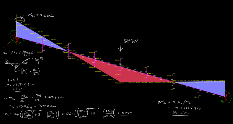
I think there might be a quick and easy first test we can apply. Taking the W27x84 and the same bi-linear shape of the moment diagram from the test case, I reduced the maximum bending moment to 1240 kNm which is the design section capacity phi.Ms. I then increased the sub-segment length until the AS4100 LTB capacity phi.Mb = phi.Ms. The sub-segment length was 5.065m (ie from end of beam to the inflection point) giving overall beam length of 20.26m before LTB governs according to AS4100.

If I may be so presumptuous, I believe KootK will have an opinion on whether this is realistic or not. If that opinion is that it is not, he may never 'drop his bone' and accept AS4100. That doesn't need to end the discussion but people may at least continue knowing that.

KootK said:
If the AS4100 provisions are so simple, derive them and post the derivation here.

I don't think this is a fair challenge. AS4100 is simple to apply. If you put aside the 'flange that moves further' and just take the compression flange as the critical flange, the challenge is deciding on whether you've got F, P or L restraints. With a small moving of the goal posts from 'simple to apply' to 'written simplistically', AS4100 is over-simple in this regard as it gives no numerical guidance - you just make a judgment, guided by some published examples of common connection details (or refer to other sources which set out stiffness requirements).

Deriving the AS4100 requirements with regard to this specific situation from first principles would be anything but simple. I suspect that many of the provisions were derived from basic cases like non-continuous beams, uniform moment etc and simply applied generally. I like to think the gurus considered the range of possible application and made a conscious (and correct) decision that AS4100 is close enough for government work but perhaps not and we just get lucky. Eg I found recently when discussing the Kt factor with Agent666 that it is known that the alpha,m factor (=Cb) can be quite unconservative for monosymmetric beams.
 
The 20.26m long beam case highlights the fact that AISC in potentially ignoring the benefits of any intermediate L type restraints is fairly savage on the capacity if you're simply forced to consider the entire 20+m length in one hit.

For a beam that size the 5.065m segment length is fairly consistent with what you might see in the negative moment region of a long span rafter round these parts.

I get a slightly different segment length 5.448m though (alpha_m =1.75, alpha_s=0.571). But could just be the degree of accuracy in converting to metric (I did work out the properties using FEM, but they were all slightly different from the tabulated values in AISC, so I just converted to metric the tabulated imperial values).

In reality if you also had F/P restraint instead of L restraints you'd get FLR in the next span that would allow you to add in k_r = 0.85 factor on the effective length for the end segment. I'd certainly consider this is a practical situation. If we were to do it here in steven49's example we'd get a segment of 5.065/.85=5.958m to squeeze a little more out of the system! Total span achieved would be 23.835m.

I'd note as well in NZS3404 E=205000MPa vs 200000MPa in AS4100. So we've got one up on you Aussies for once...

When comparing Cb's keep mind our standards typically cap the more or less equivalent alpha_m out at 2.5, and in NZ most of the time we're capped at 1.75 for seismic design. So there's another chance for AISC to claw back some additional capacity in some scenarios if what's being noting by you steven49 is true regarding Cb factors being much higher than 2.5.

I think that discussion on monosymmetric beams basically made me conclude we should be using a buckling analysis for anything but a simply supported span with any monosymmetry so we can correctly capture the buckling behaviour. For anyone interested the discussion was hereLink.


Agent666 said:
By critical buckling analysis I mean an eigenvector/eigenvalue type analysis (I forget which one exactly), mastan2 calls it elastic critical load. I believe you're doing the equivalent of a 1st or 2nd order elastic or inelastic check which requires the 2nd order effects to be allowed for. So if you haven't allowed for them in the output your mode of failure may be different so not clear if you would see the same tension flange thing going on (probably will).

I've been doing both eigenvalue buckling analysis and non linear. Both have yielded results with 5% of each other. I have reasonably good faith that the buckling analysis that I've been doing is representative of a perfect beam. The results line up very accurately with theoretical buckling. Of course what it doesn't do unless I push it is model imperfections, so it will be expected to overestimate things. But it is still useful to do comparisons like mention below, where 2 restrains according to AS4100 make zero difference to buckling whereas logic suggests they do.


Agent666 said:
The 20.26m long beam case highlights the fact that AISC in potentially ignoring the benefits of any intermediate L type restraints is fairly savage on the capacity if you're simply forced to consider the entire 20+m length in one hit.
I completely agree. 4100 seem overly conservative in their treatment of beams with moment reversal. In the case of my earlier example of an 8m 250UB31 beam. Top flange restrainst 1m in from each end make no difference in effective length according to AS4100. Wherea in buckling analysis they show that they increase the buckling capacity by 100%. AISC as described by Kootk sounds worse by not even considering the top restraints. (But maybe I've misinterpretted Kootk and I don't know AISC.)


I'm almost become a little bored of this discussion. That said I'm happy to contribute. If anybody has a specific set of anaylis to run I can do that. I did start doing a bit but then I lost direction and motivation. I did start a set of tables comparing as4100 to linear buckling results but to do it properly I'd need many dozens of scenarios.

The fact that AS4100 (and other codes) doesn't mimic true buckling shouldn't be a surprise. The code attempts to apply simple rules to approximate real world buckling behaviour while staying conservate. Given the infinite permutations involved it is impossible to consistently match the curve. So what we get is a code that is sometimes 50% conservative and other times 150% conservative. Could it be improved, of course. But what is the best way to do this without needing buckling analysis in the code and while staying simple and conservative.


Oh and as far as real world engineering goes. A fair bit of this has relevance for the work I do. I pretty much mostly do steel structures for manufacturing plants. A few times this year things have popped up which have meant that I've had to delve deeping into buckling assumptions. EG; a detailer which created a discontinuity in the plan bracing system to prevent lateral buckling.
 
Human said:
Top flange restrainst 1m in from each end make no difference in effective length according to AS4100. Wherea in buckling analysis they show that they increase the buckling capacity by 100%

The original simplified rule for identifying critical flange on gravity beam was the top flange (vice versa for uplift). So the simplified critical flange check (ie without doing a buckling analysis) used to consider these lateral restraints on the tension flange. When they generalised the simplified rule to “compression flange” we’ve ended up at this funny situation where one joist or purlin is as good as a full restraint and yet the very next joist or purlin is considered completely useless.


Human said:
If anybody has a specific set of anaylis to run I can do that.

Could you possibly do the 1m restraints on the bottom flange (ie according to code “compression flange” rule), and compare to the top restraint case? Be interesting to see the difference.
 
I'm hanging out for an elastic buckling analysis of the W27x84 (32 foot span) test case so we can see what AS4100 gives using the alternative method. If Yura is right, the capacity should be something like half of the AS4100 hand method.
 
steveh49, I'll try setup the following cases over the next few days in mastan2:-

1. no intermediate restraints as per AISC.
2. adding only the L restraints in the middle portion where the top flange is in compression (comparable to how you would apply the code provisions).
3. all L restraints to the top flange as per original sketch.


Tomfh said:
ould you possibly do the 1m restraints on the bottom flange (ie according to code “compression flange” rule), and compare to the top restraint case? Be interesting to see the difference.
General configuration; 250UB31, 8m, pinned ends with full flange restraints, load on top flange in centre of beam, moment added at ends to get inflection at 25% and 75% along beam. liner(eigenvalue) analysis
No restraints buckling result 43.7 kN AS4100 limit: 32.1kN 36% margin
Top restraints @1m&7m buckling result: 90 kN AS4100 limit: 32.1kN 181% margin
Bottom restraints @1m&7m buckling result: 70 kN AS4100 limit: 41.6kN 68% margin

As previously discussed AS4100 falls over completely at top restrains on the top tensile flange when buckling analysis shows that this is the critical flange wherase rigid application of the compression flange rule says the opposite.


Keep in mind if you're truly doing an eigenvalue analysis then you are only working out the elastic buckling bending moment, you still need to apply the relevant code clauses to this result to get the capacity. The result from the buckling analysis is not the code capacity like you're implying (unless you're actually reporting this, but I got the feeling you're just reporting the value straight out of the analysis?) Just wanted to point this out in case someone ran off and used the numbers straight out of the analysis and thought they were 'doin it right' [dazed]

You still need to apply the code buckling curve essentially, with an eigenvalue analysis you're just working out the theoretical buckling load, you apply the normal alpha_s after that which accounts for the imperfections, residual stresses and all those good old 2nd order effects.

Refer to clause 5.2.4, etc, I'm the first to admit this clause is not written very clearly though....
 
Agreed. For brevity I neglected to repeat all those caveats. (Regarding 2nd order effects. Non linear buckling analysis has yielded very similar results to eigen value. In fact it the values are often higher. (Going out on a limb speculation: Minor deflection of the beam lowers the load and reduces the potential energy available for buckling. So actual buckling occurs at slightly higher loads.)

No imperfections etc have been includeded here.
 
steveh49, results below for an elastic buckling analysis in accordance with AS4100/NZS3404 for kootks test case. Same capacity more or less as human909s Spacegass test calculation (phiMbx = 544kNm vs 543.6kNm). Not entirely unexpected.

Haven't worked out the alpha_ m factor using the elastic buckling analysis method, but don't think it will change.

Annotation_2019-11-18_222653_xmezdl.png


For case 2, phiMbx = 1206.7kNm (not quite FLR)
For case 3, phiMbx = 1240kNm (just made it over FLR condition)
 
Agent, does that show buckled shapes for those cases?
 
Sure, though I will say once you start working with restraints that are not on the member centerline, the answer does become sensitive to what stiffness you have to represent the web upstand for locating the restraint at the flange level. I've found taking a bit of plate equivalent to the beam depth at the web thickness seems to give a lower bound type approach representing some some deformation in the web to centerline. In reality the continuity of the flange spanning horizontally probably helps. No real bench-marking of this approach though, just engineering judgement. If there were stiffeners I'd make it stiffer.

Note that the scale is severally distorted here (scaled up ~400x)
case1_lrkqja.png

case2_n0n2bi.png

case3_ubdizy.png
 
For case 1 if I determine alpha_m via the buckling analysis, for the alpha_m=1.0 scenario the buckling moment is 416.5kNm. (note very close to the alpha_m calculated in post above from the table 5.6.1)

So alpha_m = 718/416.5 = 1.724 (vs 1.71 calculated via the table for alpha_m.

These results for case 1 are not unexpected, after all the equations in the code are intended to represent the theoretical buckling behaviour. The buckling analysis is simply solving the underlying finite element derivation for lateral torsional buckling.
 
Status
Not open for further replies.

Part and Inventory Search

Sponsor