Continue to Site

Eng-Tips is the largest engineering community on the Internet

Intelligent Work Forums for Engineering Professionals

  • Congratulations KootK on being selected by the Eng-Tips community for having the most helpful posts in the forums last week. Way to Go!

Salesforce Transit Center closes due to cracked support beam 16

Status
Not open for further replies.
Replies continue below

Recommended for you

Ingenuity said:
Really, only 100 ton capacity...from a hydraulic/ram area perspective they look like closer to 1,000 ton capacity.
I think the limiting factor is the telescopic part of the shoring. It looks to be made of aluminum.

Google Streetview's time machine gives a good look at the Bus Level steel. The central N-S Floor Beam is spliced in two places. The splices are just outside the line of the central columns. The 1st St. & Fremont St. steel is slightly different.
1st St: Link

Fremont St: Link

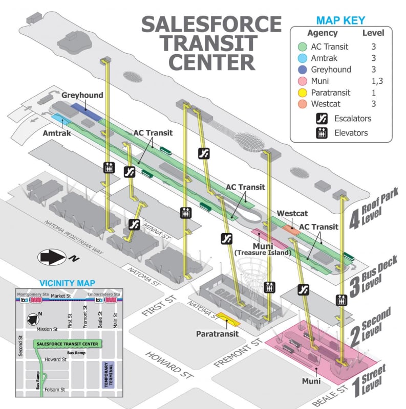
transit_center_3d_map_draft_ver03-01_bbi8gf.jpg
 
"So in the SF Bay Area erected structural steel work goes for about $8,000 per ton..."

Most of our bridges are about half that, but some of our more complicated sign structures, with big curved pipes, catwalks, railings, etc. are in that price range.

Scrap steel has been between $0.02 and $0.05 per pound, if you take it to one of the actual scrapyards and throw it on the pile yourself. The other recyclers have a dumpster that you can throw it in for no money either direction. Old car batteries are where the money's at.
 
@hpaircraft: Thanks, article correct with your input!

Roopinder Tara
Director of Content
ENGINEERING.com
 
@IRstuff: Thanks for your comment. It was an odd phrasing. Corrected.

Roopinder Tara
Director of Content
ENGINEERING.com
 

An excerpt- "San Francisco city officials are withholding $9.6 million meant to fund expansion planning for the Salesforce Transit Center, in a bid to hold its leadership accountable for alleged mismanagement of the $2.2 billion project."

That's the funniest thing I've ever heard.

Brad Waybright

It's all okay as long as it's okay.
 
Should read further down:

"Instead of paying contractors who try to make up deficiencies, they witheld payment to Webcor/Obayashi and some of the (subcontractors)."

[neutral]
 
samdman21 said:
Instead of paying contractors who try to make up deficiencies, they witheld payment to Webcor/Obayashi and some of the (subcontractors)."
...who have now sued the TJPA for $150M for breach of contract.

Brad Waybright

It's all okay as long as it's okay.
 
"Towering Over The Bay", title of the latest Civil Engineering ASCE magazine featured on the cover. Article starts on page 44 and continues to page 53. Impressive.
 
Has anyone considered the ASIC provisions for transverse stiffeners? Specifically, I'm looking at AISC 360-05, section G2.2 which says, "The weld by which transverse stiffeners are attached to the web shall be terminated not less than 4 times nor more than 6 times the web thickness from the near toe to the web-to-flange weld." I think it's in section 3 in 360-14?

In graduate school, I underlined this sentence with a note that full-depth stiffeners may cause cracking in the flanges. That is, the welding of the stiffener to or close to the flange will reduce the ability of the flange to strain properly, and instead the flange will crack. It's a different condition if the stiffener is located at a support....

Perhaps this has been pointed out -- I haven't read the whole thread, but didn't see anything about this section after a quick page search.

Thanks.
 
Aves85 said:
Has anyone considered the ASIC provisions for transverse stiffeners? Specifically, I'm looking at AISC 360-05, section G2.2 which says, "The weld by which transverse stiffeners are attached to the web shall be terminated not less than 4 times nor more than 6 times the web thickness from the near toe to the web-to-flange weld." I think it's in section 3 in 360-14?

In graduate school, I underlined this sentence with a note that full-depth stiffeners may cause cracking in the flanges. That is, the welding of the stiffener to or close to the flange will reduce the ability of the flange to strain properly, and instead the flange will crack. It's a different condition if the stiffener is located at a support....

Don't think I agree. Full-depth stiffeners are pretty common. Haven't designed plate girders since school but I had thought that you actually needed full-depth stiffeners to consider tension field action, partial depth stiffeners won't cut it. You also see full-depth stiffeners used pretty commonly in beam-column moment connections as well.
The sentence immediately preceding the 4-6 web thickness requirement discusses stopping stiffeners short of the tension flange when you don't need the stiffener to bear on the tension flange to resist a concentrated load or reaction (like you would for tension field action or stiffening a column at a moment connection). So I've always consider this 4-6 web thickness requirement to be specific to partial depth stiffeners.
 
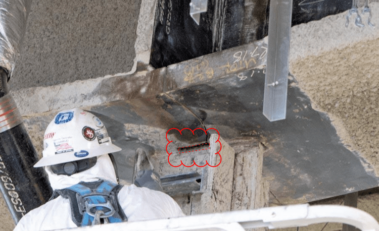
Looks like a very tight re-entrant corner. Maybe there were some flaws in the original plate that opened up into cracks once real load was put on the joint?

crackedbeam_gjfe1c.jpg


2nd_Crack_Discovered_at_Transbay_Transit_Center__Officials_ukqwnx.jpg
 
Well MrHershey and Ave85, I think you're both correct. The stiffeners for plate girders typically are full depth. However, we clip the inside corner the 4-6 times the web thickness from the flange (at the web) and 3/4" from the web (at the flange). We then hold the welds back a 1/4" from the end of the clip.

Edit: Apparently, some like VDOT and WSDOTclip the stiffeners, as we do. Others may not, but I don't know of any that currently detail transverse stiffeners without a clip.
 
MrHershey said:
Don't think I agree. Full-depth stiffeners are pretty common. Haven't designed plate girders since school but I had thought that you actually needed full-depth stiffeners to consider tension field action, partial depth stiffeners won't cut it. You also see full-depth stiffeners used pretty commonly in beam-column moment connections as well.

Sure. Maybe I mis-typed. I'm not pointing to full-depth stiffeners. I'm pointing to full-depth welds. Welding is known to reduce the strain capacity of steel, which is why I think the code requires that welds be held back from the tension flange. I think this is specific to web stiffeners on plate girders, and there are different requirements for moment connections, concentrated forces on WF shapes, panel zones, protected zones, etc.
 
"The holes were added after shop designs were submitted for approval. So, Herrick crews first built a set of girders without the holes and then had to build a new set of girders with them included, he said.

“Why they were added, that’s more of a design issue than a fabrication issue,” Hazleton said. A representative from Thornton Tomasetti, the design firm, declined to explain the purpose of the holes."
 
ENR has some additional info on the hanger plate and flange holes: Link

The flange holes appear somewhat contentious between EoR and fabricator - why were they were added and who requested them.

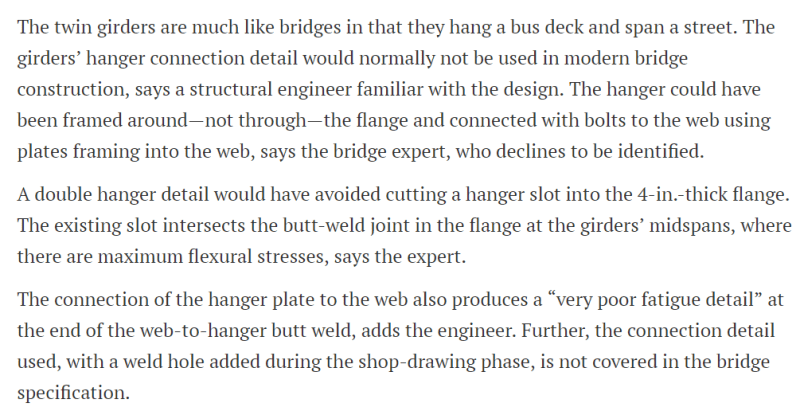
Interesting place to locate two 2" x 4" flange holes (each side of web), and allow a hanger plate to pass through, so as to connect the back-to-back vertical channel hangers.

CAPTURE_ENR-SALESFORCE_hiutl4.png


CAPTURE_ENR-SALESFORCE2_sxisbg.png
 
At what point should this design have been done per AASHTO instead of IBC/AISC/AWS?

It looks like a lot of CYA will happen as to how the holes should have been finished. However my quick scan of AWS doesn't seem to say a weld termination finish in cyclically loaded structures to be different than weld access holes.

AWS D1.1 - 2000

5.17.2 Group 4 and 5 Shapes. For ASTM A 6 Group 4
and 5 shapes and built-up shapes with web material
thickness greater than 1-1/2 in. (40 mm), the thermally
cut surfaces of beam copes and weld access holes shall
be ground to bright metal and inspected by either magnetic particle or dye penetrant methods. If the curved
transition portion of weld access holes and beam copes
are formed by predrilled or sawed holes, that portion of
the access hole or cope need not be ground. Weld access
holes and beam copes in other shapes need not be ground
nor dye penetrant or magnetic-particle inspected.
 
An update in ENR:
ENR said:
A combination of:[red]
1. Low fracture toughness deep inside thick steel plates,
2. Cracks present as a consequence of normal steel fabrication and
3. Stress levels from loads, which are a function of design[/red]

apparently caused brittle fractures in the bottom flanges of the center's twin built-up plate girders that span 80 ft across Fremont Street.

All three ingredients were needed for the brittle fractures.

“Take away any one and there is no brittle fracture because the other two compensate,” says Michael D. Engelhardt, a professor of engineering at the University of Texas, Austin

Check out Eng-Tips Forum's Policies here:
faq731-376
 
Status
Not open for further replies.

Part and Inventory Search

Sponsor