Eng-Tips is the largest engineering community on the Internet

Intelligent Work Forums for Engineering Professionals

  • Congratulations waross on being selected by the Eng-Tips community for having the most helpful posts in the forums last week. Way to Go!

Simple question about symmetry positioning 2

Status
Not open for further replies.

ApexM0Eng

Computer
Feb 23, 2015
39
CA
I would like to start integrating some GD&T tolerances into drawings, and I figured I would start with symmetry and true positioning
for features that I do often.

One concept I am trying to figure out is how to specify a hole should be centered within the width of a part.
Here the width is not a critical dimension, but whatever it ends up being I want the hole to be centered
with it within 5 thou of the center line.

So I mocked this up:
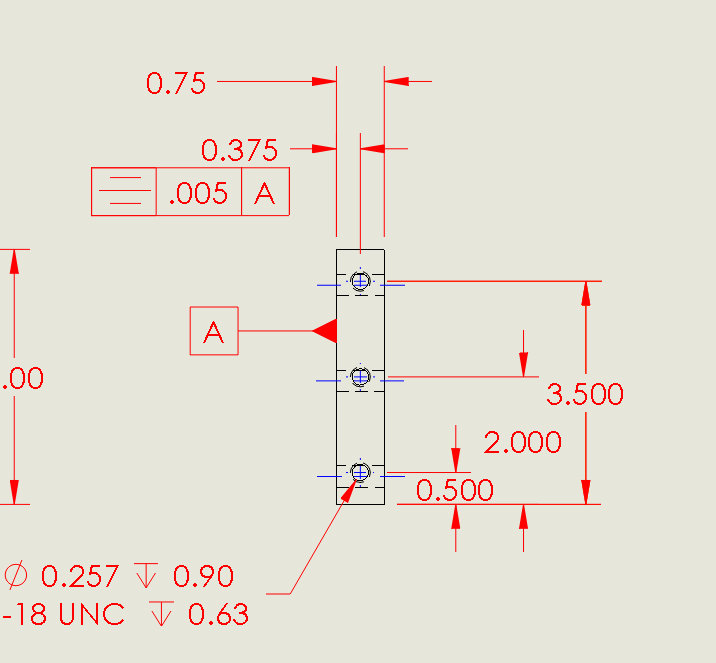
undefined_oijodk.png


But from researching symmetry positioning, this doesn't seem like the proper use. What would be the right
way to specify what I wanted?
 
Replies continue below

Recommended for you

This is not the proper use of symmetry but the bigger issue is your desire to use symmetry at all. Unfortunately ASME's definition of symmetry is not what one would think. I can see the tendency to want to use symmetry when the intent is to keep things symmetrical but it's not as simple as that. What you want to use here is position. If you are taking on the task of updating prints then you really need to have access to the standard. Look on page 116 of the 2009 standard for an example of how to locate threaded holes and read the explanations.

John Acosta, GDTP Senior Level
Manufacturing Engineering Tech
SSG, U.S. Army
Taji, Iraq OIF II
 
What happens, in an exaggerated case, if the part comes out at .5" width? Isn't the hole still going to be positioned at .375" from Datum A and be off center by a fair bit.

I am reading from page 116. It looks like you can place a Datum on a circular feature in Fig. 7-16 to get a reference to the exact center,
but I don't have a circular part. I still can't see how one positions around a center line normally.
 
ApexM0Eng,

Have you done any reading or had any training in GD&T? It sounds like we need to school you from scratch. I can inspect your part and interpret your symmetry specification. Having said that, I agree strongly with powerhound's comments. Symmetry is inappropriate for this application. You need to specify true position.

Let's take your symmetry specification seriously. Your dimension specification to the holes, .375", should be boxed, making it a basic dimension. This makes it an exact, nominal specification. Symmetry means that this actual dimension is your real thickness divided by two. If you allow [±].25" variation of the thickness, then your hole will be at 0.50"/2=0.25".

Your holes actually must be positioned in two dimensions, which is accomplished by true position.


--
JHG
 
ApexMOEng,

Reccomennd to use position instead of symmetry... the difference is symmetry is a relationship of centerplanes where what your really wanting to do here is position the holes about the center of the part, so use position.

Put the datum A attached (inline) with the .750 width dimension, make the .375 basic, remove the symmetry GDT and put a positon GDT on the hole size. This makes the datum A the centerplane of the width regardless of its produced size (it will always be the center) and uses position to locate the holes to the centerplane (within whatever positional tolerance you provide).

lightweight, cheap, strong... pick 2
 
If you wanted it on center, couldn't you do what Koda94 said, but leave off the .375 basic dimension and add a vertical center line going through the holes? By definition this center line would be center of datum A (.75 width) regardless of actual size of .75 width.
 
 http://files.engineering.com/getfile.aspx?folder=8e664e36-dfe9-4e28-95b9-355456db9d06&file=center.PNG
@drawoh No. Never received any formal education, but I want to start playing around on the side to and familiarize myself. I can understand now why symmetry is incorrect now.
So all replies are really helpful and thanks for taking the time to do so.

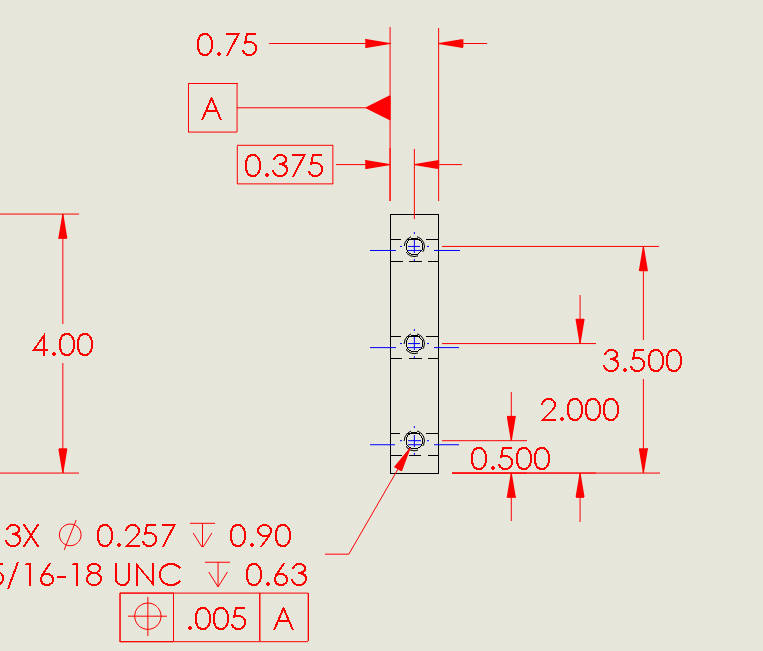
@Koda94 Like so?
I think I might have misunderstood inline with .75, because from this it looks like everything is still dimensioned from the left side.
undefined_idmjuu.png
 
If you want to have the holes centered your latest sketch doesn't achieve that.

Korda's advice is slightly off, TWJR input when taking in coordination with the correct part of what Korda says and looking at the image TWJR posted should work.

Like up the datum A indicater with .75 as Korda says.

This makes the center plane of the .75 dimension the datum.

To position the holes on this datum plane as TWJR suggests a center line should make it clear that the holes are nominally on the center line.

The position FCF is what gives the tolerance of how far away from the datum plane it can be.

Get rid of the .375 dimension.

(This all assumes ASME)

Posting guidelines faq731-376 (probably not aimed specifically at you)
What is Engineering anyway: faq1088-1484
 
As for putting inline, I was just reading page 56, figure 4-13.

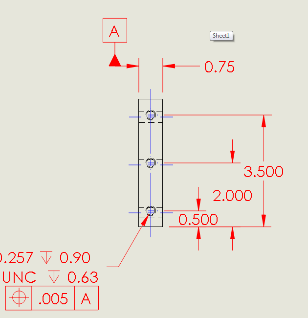
Like so?
undefined_vre1wf.png
 
Look at how the B & C datum are located on the screen clip that TWJR attached. Doing this along with the centerline (and here is where I differ slightly from TWJR) that goes all the way through the part (not just through the holes) will indicate that regardless of what the 0.75 dimensions comes in at (be it 0.749, 0.72, or 0.whatever, the datum will be the exact middle of whatever dimension the part comes out to be.

I don't believe the basic 0.375 dimension is even needed, and is probably incorrect based on what you say (holes right down the middle) you are trying to achieve. But the 0.75 should be a basic dimension

You will also need a datum for the face the current view is sitting on and a datum along the face the 0.5, 2.0, & 3.5 dimension are taken from then the 0.5, 2.0 & 3.5 should be made basic dimensions. And you true position should be with respect to:
a) the surface the part is sitting on
b) the centerline of the 0.75 target dimension
c) the datum associated with the 0.5, 2.0, & 3.5 dimensions

 
Yeah. I noticed the B & C Datums on that screen clip.
Could you explain how adding those differs from just using Datum A, if my single goal for now is just to position the holes horizontally?

Are they both right, but adding B and C better if I want to do the entire part in GD&T?
 
yes, correct you dont need the .375 basic dimension.

Apex..., see attached example for correct placement of the datum A symbol. For it to represent the centerplane of the width of the part it must be placed in line with the dimension otherwise it only represents the surface.

getfile.aspx


As far as using additional datums (-B- and -C-) is determined by the design intent of the part. Based ONLY on the description in the OP it doesnt need the extra datums if all you want is to make certain the holes line up about the center of the width. For example if the mating part is using vertical slots to attach. But if the mating part is using holes its probably better to add B and C datums and make the vertical linear dimensions basic.

lightweight, cheap, strong... pick 2
 
And if using Solidworks, there is no cute trick to attach the datum in line with the .75?

Rather to do so, will require me to attach it to the left side and drag it up to be inline.
Just curious, for functionality if I ever wanted to change the .75 position I would manually have to move
both rather than just one.
 
.75 does not need to be basic - unless there's some other tolerance issue you're concerned with that you are addressing separately.

Posting guidelines faq731-376 (probably not aimed specifically at you)
What is Engineering anyway: faq1088-1484
 
Agree with Apex & Koda regarding the need for the secondary and tertiary datum only if you need to control the hole in the vertical direction (as drawn)

side note question (not intended as a thread jack, just additional clarification):
Regarding the centerline requirement "through just the holes" or "through the entire length of the 0.75 dimension", I was always under the impression that the centerline had to go through the entire length. But after additional reading it sounds like the datum flag attached to the dimension alone identifies the datum as the center plane. However if the centerline is just through the holes doesn't it leave some debate as to whether the holes centerline and the part centerline are one in the same or did somebody leave a dimension off. ???
 
select the dimension then select the datum tool and it should attach in line and move with the dimension.

Sometimes it doesnt work for me though it attaches opposite (in this case that would be vertically) and I've had to manually place it in-line thus having to move both to re-adjust location on the drawing if needed. Solidworks is buggy like that, or it could be my installation IDK

lightweight, cheap, strong... pick 2
 
@Koda94 Doing as you said gave me the results in post #7. In that the Datum sticks up vertically, perpendicular to the dimension and not inline.

I wonder if there is a setting I don't know about.
 
Kenat, I thought part of the requirement for a TOP is basic dimensions or does the centerline qualify as an implied 0.00 basic dimension from the centerplane?
 
Apex,

sometimes I cant figure it out its frustrating, it doesnt happen all the time to me though. I know if you've rotated the view in the drawing it messes up alignment, like with using ordinate dimensions. Also try selecting the datum tool first, then select the dimension.... sometimes thats worked. I havent really figured it out, welcome to solidworks its buggy in places.


I'd like to know about the centerline question thats pertinent to this thread because I also thought the .375 basic dimension was needed. If so it needs to say 3X (or 3 places) and the centerline is not used. Its my understanding that you can only use a centerline to locate a feature if the centerline is dimensioned and the dimension to the centerline is basic. I know the .750 (width) dimension should not be basic.

lightweight, cheap, strong... pick 2
 
Koda94,

Use the centre-line if and only if you require the holes centred. More often than not, I want my holes located accurately from one side, and I don't care (much) where the other side is.

The centre-line shows that the holes are located half the thickness from one edge, making the .375" dimension redundant. If you are using 3D[ ]CAD like SolidWorks and you have centred the holes in your model, the .375" dimension will update when you change the thickness. If you want to be anal retentive, you can replace the basic dimension box with brackets, indicating that it is a reference dimension. Reference dimensions can be nasty on a drafting board, but it does not look like you are on one.[smile]

--
JHG
 
Status
Not open for further replies.

Part and Inventory Search

Sponsor

Back
Top