Eng-Tips is the largest engineering community on the Internet

Intelligent Work Forums for Engineering Professionals

Miami Beach, Champlain Towers South apartment building collapse, Part 15 32

Replies continue below

Recommended for you

IEGeezer said:
If we assume deterioration was roughly equal everywhere...any theory about the initial point of collapse would have to explain why a more lightly loaded column would fail/punch through first....Here are my rough calculations of the dead loads:

@IEGeezer, Thanks very much for contributing to the discussion on this topic. It is important to study all viable objections or alternatives to their conclusion. There are several ways in which I can predict, and show, that the deterioration was dramatically worse at the connection of the deck to the southern perimeter wall. Thank you for taking the time to compile the data and share your calculations. The figures look reasonable to me.

IEGeezer said:
I still don't see how the failure could have started at the wall.

Thanks for the additional details extending to the wall that is helpful. Please can you describe or sketch how the deck wall connection will fail if you increase the dead load to the point of failure? Or the condition after collapse of the deck at the wall if K13.1 is the initial point of failure?
 
thermopile said:
Question is did those breaks occur before slab landing on garage floor, or after part of slab landed on say an auto below, with the breaks occurring from a cantilever situation?

Yes, thanks thermopile, that is the critical point. My perspective is that it is not possible to achieve the conditions we see unless the deck cracks first in two places and detaches from the wall as a result.
 

There is simply no reasonable means by which the planters along the south perimeter can cause this collapse.

Ian, I appreciate your enthusiasm but this is a non starter.

Geezer, thanks for the calcs but they really weren't necessary.


It's good to see some numbers but I struggle with design calcs used to evaluate failures. We have here a specific case where the load is not spread evenly so for evaluative purposes, wouldn't it be better to run some numbers that recognize the known warts such as the uneven weight distribution of in situ vehicles. Even if the numbers still indicate that the building should have remained standing, we might start to appreciate where things deviated from norms. In this case, there was no mythical live load, only static loads.
 
IanCA said:
Please can you describe or sketch how the deck wall connection will fail if you increase the dead load to the point of failure? Or the condition after collapse of the deck at the wall if K13.1 is the initial point of failure?

Professor Lehman assumed a 9.5 inch slab everywhere. Morabito apparently made 5 cores: A, B, C, D, E and F. A, E and F show a 9½ inch slab. B and D show a 10¼ slab. C shows a 10½ slab. If the slab under the parking deck was intentionally built thicker, then that may or may not invalidate professor Lehman's model. I don't know. I have not found a specification for anything thicker than 9½ inches in the original drawings. For the deck to fail at the southern wall first (i.e. without any punching shear in the interior columns), I would think that the only way that could happen is if the deck failed in shear at the wall. A thicker slab for the parking deck would make that less likely. There would also have been a much smaller actual live load on the pool deck.

For the wall to pull out like it apparently did would be difficult to explain unless the interior columns failed in punching shear first, causing a catenary that would clearly have pulled the deck away from the southern wall, like so:
Catenary_jwyj2v.png


It is difficult when looking at something forensically whether it is cause or effect. Is the deck pulling out from between the southern privacy wall and the supporting wall cause or effect? I'm leaning towards effect.

I don't necessarily think that a shear failure at the southern edge would propagate so easily to the north. A shear failure at the southern wall would I think reduce the load on the columns immediately to the north, thus maybe arresting a progressive collapse (or leading to a different kind of collapse where the interior columns fail due to an unbalanced moment rather than in punching shear). Punching shear failure of the interior columns, on the other hand, would, as the diagram above shows, make the steel reinforcement act as a weighted cable that will tug at the extremities (slab doesn't disintegrate, but stays relatively intact). Thus, the deck pulls out of and off of the southern wall and away from the building, perhaps damaging certain building columns when it pulls out. For that reason, I favor punching shear failure of the interior columns and K 13.1 seems to be the most highly loaded one.
 
I agree with you on K13.1, especially since the small column footprint would concentrate the impact of shearing forces. I hesitate though in that a known decrepit slab may have been vulnerable to a special case scenario such as an excessive point load from a heavy truck. A punch out at K13.1 could propagate through the parking area sooner than the pool deck.
 
Sym P. le said:
Geezer, thanks for the calcs but they really weren't necessary.

The calculations have helped identify column K-13.1 as the most severely loaded column in the vicinity of the collapse.

Sym P. le said:
It's good to see some numbers but I struggle with design calcs used to evaluate failures. We have here a specific case the load is not spread evenly so for evaluative purposes, wouldn't it be better to run some numbers that recognize the known warts such as the uneven weight distribution of in situ vehicles. Even if the numbers still indicate that the building should have remained standing, we might start to appreciate where things deviated from norms. In this case, there was no mythical live load, only static loads.

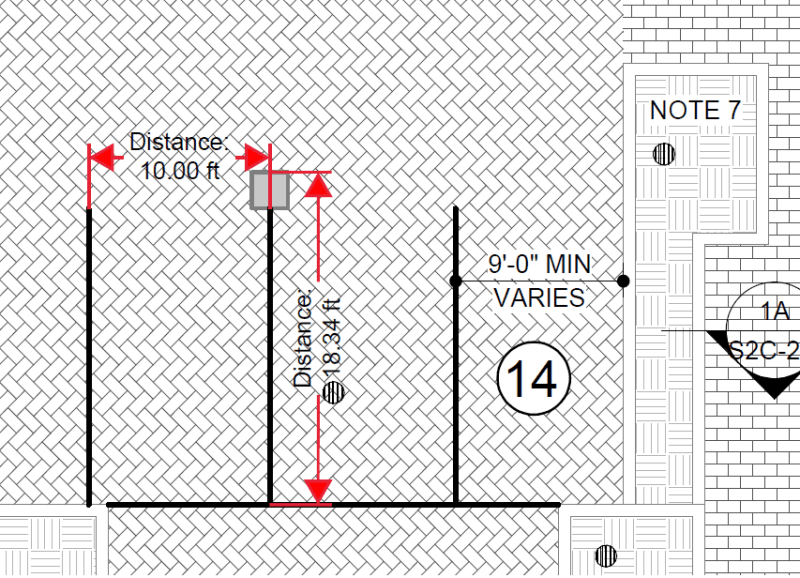
According to Morabito's Sheet A2C-1.0, the parking spaces in the area that we have been focusing on are approximately 10 feet wide by about 18⅓ feet long. Column I-14.1 would only have had 2 parking spaces in its tributary area. If you assume that you have a heavy vehicle and a sedan, the actual load for those two parking spaces would have been about 10 Kips in the tributary area for column I-14.1. Because of where the axles would have been (due, in part, to the planters), I don't think the weight of vehicles would have been attributed to the wall tributary area. So the vehicles would not have, theoretically, contributed greatly to the loads at the wall, but I would have to double check that. The thicker slab and that Column I-14.1 is bigger than K-13.1 should have helped.

Parking_spaces_mmmgfr.png


One of the reasons I have focused on the pool deck is that the dead load for it is about 168 lbs per ft², whereas the parking deck's dead load is about 171 lbs per ft² or almost the same. Yet, the parking deck is thicker and has bigger columns. Columns K-13.1 and K-15 should have been the same size as the parking deck columns.
 
Thanks Geezer, I was referring to the planter area calcs as not being necessary. The others I find useful. My concern about the weight of the vehicles is their potential impact at the slab/column connections to which they are adjacent in addition to any slab deflections to which they contribute.

I agree with you that columns K13.1 and K15 should have been considered as supporting the parking area in the original design.
 
IEGeezer said:
For the deck to fail at the southern wall first (i.e. without any punching shear in the interior columns), I would think that the only way that could happen is if the deck failed in shear at the wall.

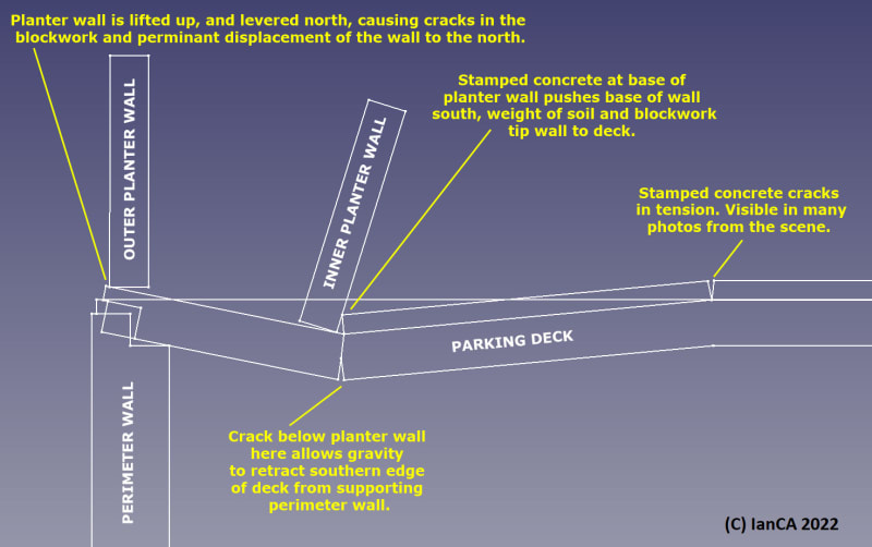
Please can you try to explain to me why you would think it would not be possible for the deck to fail in the way I depicted in the image shown below:
Southern-wall-deck-detatch-notes_hza9zu.jpg


IEGeezer said:
For the wall to pull out like it apparently did would be difficult to explain unless the interior columns failed in punching shear first, causing a catenary that would clearly have pulled the deck away from the southern wall, like so.

Thanks very much for the diagrams I find it helps the discussion. The columns we are talking about are 24"x24" columns, aligned on I, that supported the southern portion of the building that remained standing. The columns absolutely did experience some lateral deflection as witnessed by the cracks in the stucco at the south and north corners, but I have not seen any evidence to suggest that the deck was displaced somewhere between 8 and 16 inches to the north as it would need to be to allow the deck to detach from the wall.

Here are my thoughts about the three cases you illustrated:
Case 1 shows the deck still attached to I14.1, so the northerly deflection of the deck is comparable to the northerly deflection of the column and as such minimal.
Case 2 shows the deck after I14.1 punches through, I agree significantly more northerly displacement is possible in this case due to the downward displacement at the column and the length of the arc, but the top of the deck would not crack in tension (as we can clearly see it has in the photos) and at the end of the collapse, the deck would be draped against the wall as we see in zone C near the jacuzzi.
Case 3 again the top of the deck would not crack in tension and the end result would be the deck draped against the wall.​

IEGeezer said:
Is the deck pulling out from between the southern privacy wall and the supporting wall cause or effect? I'm leaning towards effect.
I don't see enough room or flexibility to allow the deck to retract at least 8" without there being at least two cracks (and I mean lines of structural failure) in the deck. We can see one of those cracks in the photos and the debris matches the presence of the other.

IEGeezer said:
A shear failure at the southern wall would I think reduce the load on the columns immediately to the north
Surely if the deck detaches from the southern wall the load previously carried by the southern wall would then be carried by column I14.1, increasing its load.

IEGeezer said:
will tug at the extremities (slab doesn't disintegrate, but stays relatively intact)
Can you estimate the lateral displacement at the southern wall, please? I think it is probably fair to say that reinforced concrete slab or deck doesn't usually disintegrate. But we can see that the conditions in this case are unusual and the concrete did disintegrate. Please see the area of the image highlighted below:
slab_disintegrated_below_parking_deck-crop_aaudqn.png


IEGeezer said:
Column I-14.1 would only have had 2 parking spaces in its tributary area.
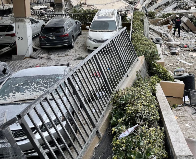
Unfortunately, the parking area encompassing spaces 44, 45, 46, and 47 had weaknesses on both sides. Certainly a construction joint to the west and probably one also to the east beneath the planter running south to north to the pool deck gate. Is there a way to explain the rotation of the planter wall and fence in the foreground of the image below, if the initial failure is column K-13.1?
south-north-planter-failure_Miami-Dade_Fire_Rescue_6_crop_uddvpl.jpg

That condition can be explained by failure initiating at the southern wall because there are multiple cracks in the parking deck (a large diagonal crack is visible behind the silver Honda) and the southeast corner is able to rotate down, lifting the north end of the wall up and right, before the column below punches through.

I completely agree that the columns on K should have been 24"x24" to support the parking deck loads, but I would also include K-11.1.
 
Sym P. le said:
There is simply no reasonable means by which the planters along the south perimeter can cause this collapse.
Please can you tell me where was the weakest region of concrete in the structure prior to the collapse and why?

Remember, none of the professional and experienced individuals who visited this property in the past 4 or 5 years felt there was any imminent danger, including the city inspector who visited the day before the collapse. So we are actually looking for something that would not conventionally be considered reasonable or expected.
 
Optical98 said:
Closer images, actually that looks to be a hard cover for the truck bed that's been dented in
Thanks very much for those images, much appreciated. I hadn't noticed the apparent hole in the wall in the channel 7 screen shot.

The explanation I have for the hard cover being dented in is perhaps that Ileana Monteagudo and/or Shamoka Furman stepped on that surface, and fell, while trying to reach the street. They are seen/heard standing right there in one of the police bodycam videos and Shamoka says the lady is injured.
 
In one of the previous threads there was a linked document where someone was trying to pin blame on 87 Park (before the whole lawsuit set of videos in this thread). One of the points made in there was suggesting that the series of images you're talking about again suggested the collapse initiated in that surface parking area - iirc either K13.1 or K15 was implied. I don't remember exactly when but if that rings a bell for one of you and you can find it quickly it's worth revisiting.

I think any rotation in the final orientation can probably be explained by falling onto an uneven surface underneath i.e. the part on the right of that image landed on a car and the part to the left didn't so it is lower and rotates the fence. Those tension cracks could be due to the loss of support after a column punches through rather than the cause as well, couldn't they?

I'm struggling to see how the slab could be pulled off the deck if it was sitting on top of it (which seems to be the case from the diagrams earlier). Even in @IanCA's diagram, it is far from pulling off entirely. Only after it punches through the 14.1/15 line would the geometry for that work for me.

If we're looking at this area of the building it seems more likely to me that the slab was starting to punch through, that was being restrained by the horizontal rebar at the wall/slab connection (providing catenary tension), and when that rebar failed it meant the punching shear was high enough to completely fail. Probably at K13.1 because all the calculations (@IEGeezer's the other day and those summarised in a BI video a few months back) indicate that is the most highly loaded and also one of the small section columns. That would then put a lateral load on the slab/wall joint and could pull it off, and the redistributed load would immediately cause a punching failure at the other columns under the deck (which were all highly loaded already).

What I'm not sure about with this idea (any of the "collapse started near the south of the deck" variants) is how it lines up with the Vazquezes not seeing anything in the garage when they drove in, or most of the reported "I heard noises" coming from the x11 stack. Yes, sounds are moved around in a concrete structure, but surely the people in the SW part of the building would have heard those noises more loudly if the initial failure was at the wall or even K13.1.
 
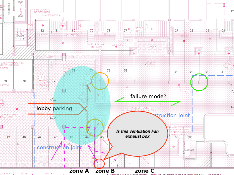
It would appear the relationship between location of pool chemicals, the ventilation fans in garage, and robust water source, would point to direction of weakest slab areas due to chemical reaction. Then there are natural designed in weakness like construction joint locations along this path, as well as other inherit weaknesses.

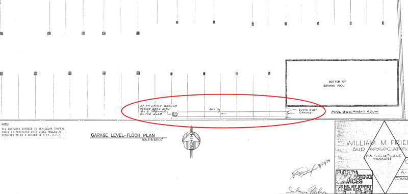
Is the box identified by the speech bubble, a potential exhaust point for ventilation fan?

EDIT: To clarify my Sakcrete comment in bed of Duramax truck. The reason the passenger rear side suspension is fully compressed is most likely just axle articulation from drivers rear tire dropping and hanging free.

A Diesel engine means that front axle is a lot heavier tire point loads than the rear axle tires. Assuming no live loads under bed cover.

Edit2: Just like roof flashing at parapet walls, any water proofing membrane under patio blocks, has to be turned up flashed and counter flashed at planters to prevent joints between finished toppings and planter walls allowing water entry. I see no evidence of that flashing system, and sagging deck due to planters drains water to this area.

Failure_mode..01.gif_vymajt_lexwjc.gif
 
thermopile said:
Is the box identified by the speech bubble, a potential exhaust point for ventilation fan?

Yes, that is exactly what that is. The ductwork is shown on sheet 22 of 336 in the 1979 plans.
There is a 30x10 duct from the pool equipment room to EF-23 via a 19x19 opening on the pool deck as shown below:

Pool-equipment-room-ductwork2note_kwzhvc.png


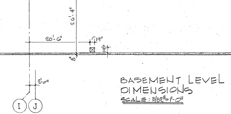
But the detail for the opening on sheet 33 of 336 (S2 of 14) was inaccurate because there was a dimension missing for the distance of the opening from the wall:
19x19-opening-on-slab_bjrdax.png


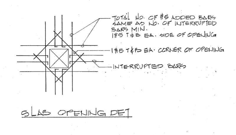
Which would make the framing detail shown on sheet 38 of 336 (S11 of 14) difficult to follow
Slab-opening-detail_ebrcbm.png


We already know that the atmosphere in the pool equipment room was detrimental to the concrete from the photos taken by the pool service guy a day or two before the collapse. I acknowledge that the loose concrete in the pool equipment room had been removed in preparation for repair, so it looked somewhat worse than it would have otherwise. But the effects of the chemicals are still significant.
 
Red Corona said:
Even in @IanCA's diagram, it is far from pulling off entirely.
@ Red Corona, thanks for your input. That diagram was at a time fairly early in the sequence of events I am proposing. I will create another showing the positions later in the sequence.
 
IanCA, So we have interrupted rebar at opening, that could be in a line under inner planter wall and great location for chemical reaction to concrete
 
thermopile said:
So we have interrupted rebar at opening.
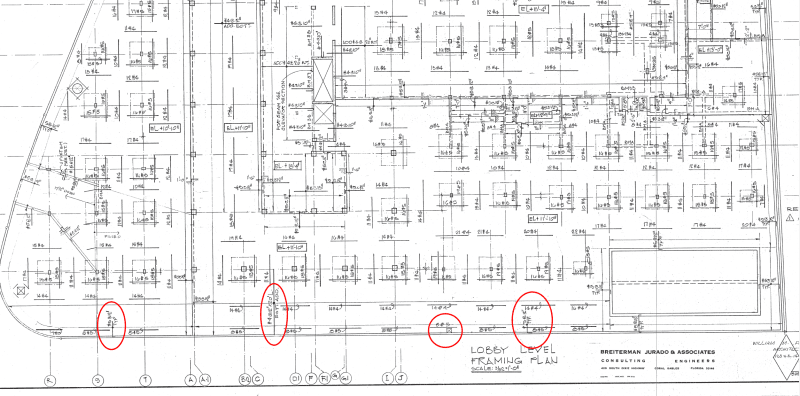
@thermopile Yes, but as far as can see on sheet 31 of 336 (S5 of 14) the bars in the deck along the wall were on 12" centers, so it would be one or two bars, top, and bottom.

Lobby-level-framing-plan-note_qnncvm.png
 
IanCA, Understand not many bars but if also a N-S or E-W construction joint in area, coupled with chemical reaction in area, things get very interesting in this area.

And missing beam from design change
 
Red Corona said:
I don't remember exactly when but if that rings a bell for one of you and you can find it quickly it's worth revisiting.
@Red Corona, Thanks for the suggestion. I suspect you are thinking about the post by IEGeezer (Industrial) on 20 Aug 21 04:34 in Part 11.
The linked document is here:
Link

I will review that information again in detail.
 
I don’t see how we avoid considering the effect of South Planter distributing loading on slab that translate to an increased load on slab connection at I14.1 of K?
 
Status
Not open for further replies.
Back
Top