Eng-Tips is the largest engineering community on the Internet

Intelligent Work Forums for Engineering Professionals

  • Congratulations waross on being selected by the Eng-Tips community for having the most helpful posts in the forums last week. Way to Go!

Miami Pedestrian Bridge, Part IV 74

Status
Not open for further replies.
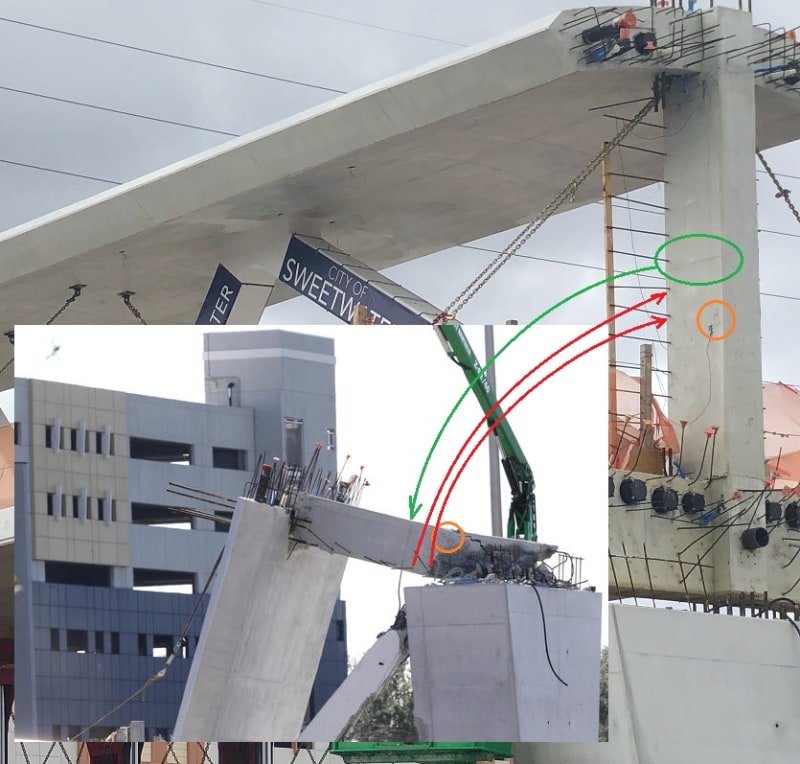
There appears to be a cold joint in 11-12 at the top of the deck. See photos above. If the PT rod(s) is anchored below that point, somewhere lower in the deck, and you increase the PT force, you increase the shear along the cold joint.
 
gwideman just beat me to it.
 
gwideman, your diagram does make sense, the lower PT bar did in fact stay with deck (it zippered out of 11), and the upper one stayed with 12 after collapse.
 
I searched for images with reference points and angles in same plane and mixed with a software editor capable to work with layers and transparency, GIMP in my case.
Images used:
POVS01_eqk8np.jpg


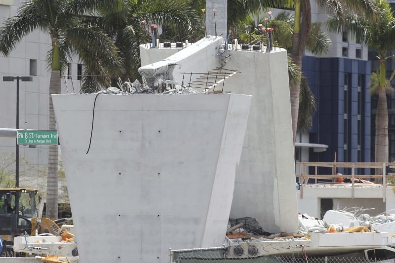
Confirmation for north end of deck:
DeckEnd01_jd7koz.jpg


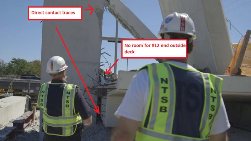
No traces from end of #12 outside deck:
PilTraces_vhodqo.jpg
 
@Meerkat 007: Nice! Well done finding images with same orientation. I imagined you had some clever technique that rotated 2d images in 3d to get them to align.
 
...you computer guys/gals...us poor structurals still talk about (and some of us use) slide rules...fancy digital re-construction. Nice.
 
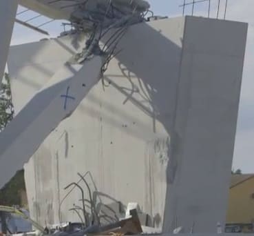
I am rethinking the shear surface. The skid marks and impact on the pier are along each side not in the center where the extension of member 12 would have impacted and slid. Perhaps the failure occurred through the white pipes with red on top. The photo of the NTSB worker digging through the rubble looks like there is a void between the two sets of white sleeves. The pipes would have made a weakened shear surface. Thoughts?
 
Concrete of member #12 base was pulverized before north deck end fall.
You can still see skid marks of like 2 rebars on pier surface.
 
RetiredSE said:
I am rethinking the shear surface.
Yes, I had been thinking similarly, and yes those pipes/sleeves seem a weak area.
I wonder what apparatus was supposed to act against #11's horizontal force. What is visible in the ntsb picture is the set of vertical rebars to the extreme north (left) of the picture, that presumable were inside #12. Their other ends perhaps fold in an L-shape under 11, and extend horizontally southwards into the deck, perhaps for some length. The tension in those rebars would produce compression in the north end of the deck, resisted by the deck tendons. If that was the entire apparatus, and if the vertical portion of the "L" bars broke out of #12, then 11 and 12 move north.
 
Note the white pipe in deck is matched on canopy if I'm not mistaken. The bar couplers shown on NTSB deck photo connect bars up to canopy? The rebar (looks like tv antenna) on 12 may have been meant to tie 12 with other section simply to form hexagon shape shown in plans.

AR-303209450_heuw30.jpg
 
I have taken the liberty of taking the Miami Herald video and breaking the order of construction down into 13 stages. These are screenshots from the video. For clarification every step is self evident with a couple of exceptions. Between stage 9 and 10 it is not clear to me if all of the web members were poured at stage 9 or if they were poured monolithically with the canopy in stage 10. This is important only from the point of view of where the cold joints probably are.

Stage 1 base for structure is completed
Stage 2 formwork for bottom flange completed
Stage 3 Vertical formwork for web members completed
Stage 4 sides of web members formed against vertical backing
Stage 5 PT ductwork and mild steel reinforcing placed in deck and web members
Stage 6 Bottom flange poured with cold joints near deck level in the diagonal members
Stage 7 Remainder of bottom flange poured
Stage 8 Diagonal front forms completed but not specific if web members are poured immediately leaving cold joints just below the canopy
Stage 9 Canopy is formed with PT ducts and mild reinforcing in place
Stage 10 Clear that the caps on diagonals have a cold joint at the deck and tops of diagonal members and caps to be poured separately
Stage 11 Caps over diagonals are poured
Stage 12 Equipment removed and presumably post tensioning took place.

Sequencing of PT probably Bottom flange then web members and then canopy but this is only speculation on my part.

Wanted to go through this step by step to 1) get an idea where cold joints might be in the web members to the deck an canopy and just clarify that the concrete was poured as a monolithic structure.

If someone knows how to have the photos as part of the post I would appreciate their input.


gwideman, given your assumed shear failure plane with the PT bar crossing it, tension in the bar would create shear friction, a clamping action tending to keep the two interfaces in contact. If the bar was detensioned, this would tend to reduce the shear friction and increase the likelihood of failure. Because the bar was in an ungrouted duct, the bar itself would offer little resistance to a shear failure, and given the other elements in the vicinity of the joint tending to reduce the effective area resisting shear, such as the 8" drain pipe and other ungrouted PT ducts, removing tension in the bar could cause failure.

I assume the bar was being detensioned because the PT was primarily required for the transport operation. Once the girder was seated on the pier, and compression introduced into member 11, the need for the PT, for the sake of strengthening member 11, would become unnecessary. We don't know if the hydraulic jack operator was just starting the detentioning process or was nearing its completion. It is possible that he was at the end of the detensioning process when the bridge failed.

Additional comment: There does not appear to be any actual joint reinforcement of the type one would find in a bridge designed to resist seismic forces. This type of reinforcement would have helped confine the concrete in this high stress zone, making it more ductile and less prone to a catastrophic failure. The innovative design, the lack of redundancy and the high stress concentration at the interface between the deck and diagonal would have made joint reinforcement a prudent choice. It would have added little to the cost of the design while providing a substantially more robust structure.
 
Just a general blood pressure warning - do not search YouTube for videos of people explaining this. I would suggest cat videos instead.
 
I agree with JRS87's posting/theory, "This bridge failed because deck separated from joint 11-12. Half the steel of 11 went with deck, the other half went with 12. Joint burst and beam zippered."

I have followed this disaster closely since I first saw pictures of the bridge on the news. The design immediately concerned me. It just looked too fragile with clear points of highly concentrated shear. I have read every comment on this thread and appreciate learning a lot from the community. At this point, I feel the design was inadequate and the bridge bound to fail. I share my assessment based on many years of practical operational and management experience. I am by no means a bridge or structural expert, I look forward to further discussion on this thread and to studying more expert and complete assessments as they are shared.

One point in support of this theory that I would highlight relates to the excellent time-lapse footage of the collapse from a dash-cam video created by Zac Doyle and linked earlier in this thread. I've watched this video many times, trying to catch the first sign of failure. If one watches the left edge of the bridge, on the backside of member 12, opposite the 11-12 joint, a small bulge appears at 16/17 seconds. I believe this is the initial separation of joint 11-12 from the deck. Thanks to Meerkat 007 for first pointing out the small bulge and for first linking to this helpful video.
 
From the concrete pour sequence we know that at the ende of 11 and 12 there is a cold joint in the concrete near the deck (not great in shear) and not a lot of mild steel reinforcing to transfer shear - this joint in my opinion definitely failed and caused the collapse. Not enough normal reinforcing to result in a more elastic failure.

 
I think this video may answer appster's question: at 1:35 it looks like the members were poured before the canopy.
 
emba
Suspected that but now it appears to be confirmed. So still a cold joint at the top of the web members probably slightly below the joint with the canopy. If so this would be a weakened shear plane if no sufficient plain rebar and stirrups.
 
Status
Not open for further replies.

Part and Inventory Search

Sponsor

Back
Top