Eng-Tips is the largest engineering community on the Internet

Intelligent Work Forums for Engineering Professionals

Miami Pedestrian Bridge, Part IV 74

Status
Not open for further replies.
I think this is what is seen beyond the North end of the bridge before collapse. It defies gravity far too long.

UFO_2a_yurvkl.jpg


UFO_1_wxbzmo.jpg
 
Weakening the concrete around the primary joint on the most critical truss member node by multiple large holes for rainwater drain pipes.
 
epoxybot you think it was rebar and white cloth? Possible, but hard to believe it would appear so fast and look so large on the video, its the only thing that changes exactly half a second before the collapse, maybe it was from the shear? or PT blow out? or perhaps a cloth or illusion like many are saying. Hard to tell.


I also found some photos that look like they might show the base of 12?

bridge_blow_iidmpo.jpg
 
What is the procedure for tightening or loosening PT at #11, which has 2 PTs? Or any PTs in general for that matter.

Assume both PTs in #11 are tightened to their max compression load and you want to loosen them. Do you loosen both simultaneously (so you will need two jacks)? Do you loosen one a little bit, then switch to the other and loosen a little bit, etc? Or do you completely loosen one PT while leaving the other PT still at max compression?

And if it is the latter most case, does that differential stress induce bending moments on the beam enough to cause problems in this case?
 
engibeer: When something may be in a state of impending collapse... changing the load regime at any location may not be a really good idea <G>.

Dik
 
dik said:
engibeer: When something may be in a state of impending collapse... changing the load regime at any location may not be a really good idea <G>.

Dik

??

Uhhhhh... yeah of course if you already knew a priori that it was an unstable structure. And if you knew it was unstable, no sane person would change the loads in a way that will cause it to fail. Also, no sane engineer would design and build an unstable structure to begin with either.

But I don't see how your response relates to my question. My questions concerns post-tensioning procedures in structural members that have multiple PT tendons. Obviously simultaneous tightening or loosening is the most ideal to eliminate bending moments, which are obviously not ideal. In this case, I see jacks on only one PT bar of the two total in #11, which will introduce bending moments to #11 if they just released or tightened one PT bar the full load range at a time.
 
Under normal circumstances adjusting the post-tensioning would be normal. It would be interesting to see what the crack was; that might indicate otherwise.

Dik
 
Newbie here.

Ingenuity said:
For member #11 with 2 each x 1-3/4" PT bars on a 24" x 21" concrete cross section, with PT bars stressed to about 70% of UTS - that is about 540 kips over about 500 in2 of concrete - so about 1,000 psi of axial compressive stress. Self weight support reaction of 950 kips and a member #11 angle of 36o equates to a compressive force of about 1600 kips (3,100 psi axial compressive stress) - add the self weight force to the stress induced by the PT to member #11 and you get a net of about 2,140 kips (or 4,100 psi axial compressive stress). IF (big IF) there was a 10% overstress to PT bars that would only increase the force (and stress) by 54 kips (100 psi) to the cross section, for a total of about 2,200 kips (4,400 psi).
Close enough.
Ingenuity said:
For 8,000+ psi concrete, adequately reinforced with mild steel reinforcing, (including significant confinement reinforcement) and the level of stress to the member should be okay...
2,200 kips is not "okay" for member #11. Far from it.

When calculating the maximum allowable design factored load for a concrete column there are other multiplication constants which reduce the design load considerably, as these university lecture notes explain.


Here's a worked example from the same notes, which I have written on top in red ink to calculate the factored load for member #11.


So member #11 is good for a maximum allowable design factored load of only about 2000 kips.

Then you have to divide 2000 kips by a safety load factor to estimate the maximum service load and then you find that the dead load of the bridge alone is barely "okay" for member #11.


This tells us that only calculating with a risky safety factor of only 1.2 can we assess that the truss member #11 is just barely strong enough to hold the bridge up with no additional load from post-tensioning bars or from any pedestrians on the bridge. Using anything more cautious for a design safety factor would warn that the bridge is at an unacceptable risk of coming down.

Of course it would be much worse if there were any issues with the concrete not being as specified.


So we can see that the bridge designers were gambling with people's lives even before a single PT bar of member #11 was post-tensioned.
 
PeterDow said:
Newbie here.

Welcome... great post...

Should have added, for concrete trusses, moments would be included to minimise cracking due to a brittle material. With high axial loading, moments may or may not be significant.


Dik
 
Peter Dowe said:
This tells us that only calculating with a risky safety factor of only 1.2 can we assess that the truss member #11 is just barely strong enough to hold the bridge up with no additional load from post-tensioning bars or from any pedestrians on the bridge. Using anything more cautious for a design safety factor would warn that the bridge is at an unacceptable risk of coming down.

What is the code required safety factor to use for self weight (or dead load) for this specific application in the US? In Australia it would be perfectly acceptable to adopt a safety factor of 1.2 for dead load under ultimate conditions.

** Edit** I should clarify that actually in this specific case considering there is little/no live load present, a load factor of 1.35 in accordance with Australian loading code would be the governing case

Peter Dowe said:
Of course it would be much worse if there were any issues with the concrete not being as specified.

This is partly the reason why a reduction factor of 0.65 is factored into the column design itself.

Peter Dowe said:
member #11 is just barely strong enough to hold the bridge up with no additional load from post-tensioning bars

Do we know how much stressing was applied to these temporary PT bars? They may have chosen to only moderately stress these bars to reduce unsightly cracking in member 11 due to temporary tension loading during lifting/transport, there may not have been a reason to wind them all the way up to 70/80% of breaking limit as per standard, especially if they knew that the loading in this member was designed so lean (which hopefully they did know).

Overall you may have simply proved that the design was economical in nature and not "over-designed". With the compounding safety effects of the 0.65 reduction in member capacity as well as over-estimation in applied load of 1.2, this appears to be code compliant (noting I'm not intimately across the US concrete/loading codes).

With the capacity being very close to the final case loading however, there may be some merit in the assumption that the designer assumed that the CHS cable stays do in fact share some of the loading in service conditions.

 
The applicable US code would be AASHTO LRFD. The load factor on DC (dead weight of components, i.e. self weight) is 1.25 for this situation. The load factor on LL, which was essentially nil at time of failure, is 1.75.
 
Noob question from a non-Civil engineer... (non-Civil discipline as opposed to un-Civil demeanor)

IF a tendon snapped, say that one with jack attached that's protruding from the blister;
THEN would an impulse result as the member elastically expands upon sudden reduction in compressive force?

Per Peter Dow's quote above of Ingenuity's numbers that'd be an instantaneous reduction in compression from perhaps 4400 to 3900 psi ?

Seems intuitively that'd be a shock not unlike a hammer blow to the joint at each end of 11, opening the fracture mechanics can of worms.

No offense if you dismiss the thought as ignorance - just i'd not seen it considered. I'm more of an electrical than a concrete guy.
We're all ignorant just on different subjects...

old jim


Never trust a computer with anything important...
 
old_jim, there is already evidence that the tendons are intact; therefore there was no shock load.
 
Member #11, #12, north deck and canopy position after collapse without deformation/destruction.
Damage01A_ncuhqc.gif


Any find something wrong, point me about please for recheck.
 
3DDave (Aerospace) said:
old_jim, there is already evidence that the tendons are intact; therefore there was no shock load.
I'll recheck about PT rods as something on my working drawings not fit.
 
Peter Dow is accurate with the equation with the design axial force.

Diagonal #11 has a slope of about 1v:1.38h based on the prelim drawings. This results in an unfactored dead load force = 1619 kips based on the truss end reaction of 950 kips.

Columns that fail when tested to failure break at mid height. The end diagonal #11 did not fail in axial compression.

I tend to agree with Ron that the failure occurred at the top of diagonal #11 and #10 in the canopy slab at least based on what the video shows.

As the bridge starts to fail the largest downward movement is at the joint where diagonals #11 and #10 intersect. Concrete in that intersection seems to burst north and south of the canopy blister. As the bridge continues it collapse the base of diagonal #11 does not shift north as one would expect if the connection between the diagonal #11, end vertical #12 and the bottom deck fail.
 
bobwhite said:
Peter Dow is accurate with the equation with the design axial force.
Thanks!
bobwhite has edited his post so I have edited my reply - before it said
bobwhite said:
Peter Dow is accurate with the equation except that the design axial force using his assumed reinforcement is about 2178 kips, f'c = 8500, 10-#7 fy = 60000 longitudinal bars equivalent to 6 sq in 1.19% of Ag.

My equation was right, but you reckon my arithmetic, shown in red ink here, was wrong?

"about 2178 kips" you reckon?

bobwhite said:
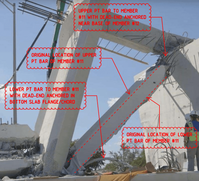
Diagonal #11 has a slope of about 1v:1.6h
Not a slope more like my force vector diagram's 1v:1.4h?
bobwhite said:
This results in an unfactored dead load force = 1812 kips based on the truss end reaction of 950 kips.
If your slope is wrong you will miscalculate the force too.
Member #11 is drawn in the engineering drawings at an angle of about 36 degrees from the horizontal, which is what Ingenuity meant with -
Ingenuity said:
Self weight support reaction of 950 kips and a member #11 angle of 36o equates to a compressive force of about 1600 kips
So "about 1600 kips" is right for the compression force on member #11 from the bridge dead load too, I agree.

bobwhite said:
Diagonal #11 has a slope of about 1v:1.38h based on the prelim drawings.
Agreed.


bobwhite said:
This results in an unfactored dead load force = 1619 kips based on the truss end reaction of 950 kips.
Agreed.
 
waross said:
I wonder if the upper PT rod in member 11 was removed after it was relieved. Is it visible in any of the pictures?

No, it was not removed.

As per the following photographs of canopy blister and members #11, #12 and bottom chord:

upper_pt_bar_eq0w5y.png


miami_memner_11_pt_bars_oroq6v.png


From a practical point, PT bars with dead-ends, and contained withIN members of considerable length are a right-royal pain to remove. The engineers would have just left them there UN-tensioned and grouted them up.
 
bobwhite said:
I tend to agree with ingenuity that the failure occurred at the top of diagonal #11 and #10 in the canopy slab at least based on what the video shows.

I don't think I said that. If I did please tell me where? Thanks.
 
Status
Not open for further replies.
Back
Top