Continue to Site

Eng-Tips is the largest engineering community on the Internet

Intelligent Work Forums for Engineering Professionals

  • Congratulations KootK on being selected by the Eng-Tips community for having the most helpful posts in the forums last week. Way to Go!

Miami Pedestrian Bridge, Part XII 34

Status
Not open for further replies.

zeusfaber

Military
May 26, 2003
2,466
A continuation of our discussion of this failure. Best to read the other threads first to avoid rehashing things already discussed.

Part I
thread815-436595: Miami Pedestrian Bridge, Part I

Part II
thread815-436699: Miami Pedestrian Bridge, Part II

Part III
thread815-436802: Miami Pedestrian Bridge, Part III

Part IV
thread815-436924: Miami Pedestrian Bridge, Part IV

Part V
thread815-437029: Miami Pedestrian Bridge, Part V

Part VI
thread815-438451: Miami Pedestrian Bridge, Part VI

Part VII
thread815-438966: Miami Pedestrian Bridge, Part VII

Part VIII
thread815-440072: Miami Pedestrian Bridge, Part VIII

Part IX
thread815-451175: Miami Pedestrian Bridge, Part IX

Part X
thread815-454618: Miami Pedestrian Bridge, Part X

Part XI
thread815-454998: Miami Pedestrian Bridge, Part XI

Check out Eng-Tips Forum's Policies here:
FAQ731-376: Eng-Tips.com Forum Policies
 
Replies continue below

Recommended for you

hokie66 said:
Without a rigorous program of testing the concept, I think this type concrete truss/frame will never be used again. And I doubt that will happen, as there is simply no call for it. Structural steel works, so why change? There was an opportunity here to load test the frame while still on the ground. That didn't happen, and disaster occurred.

Sym P. le, "advancement" is in the eye of the beholder.

The concrete truss design is not that complicated and has multiple benefits. We used to do more complicated designs by hand (as least the truss part including the non-pinned joints). However, the uneven live load distribution, aero-elastic considerations and low torsional frequencies are not so simple to deal with (but that is not the part that failed).

Multiple steel bridges have collapsed. We didn't stop building out of steel.
 
Because the steel that appears short has the same designation as the long deck reinforcing, the construction should reflect that. An RFI (Request For Information) would normally be prepared and forwarded to the proper party if a conflict arises or if more information is needed. I would expect that to be in the project file, with a response and perhaps directions or details from the EOR to provide guidance to the field.
The contractor would be assuming unnecessary risks should they make changes without guidance or approval.
 
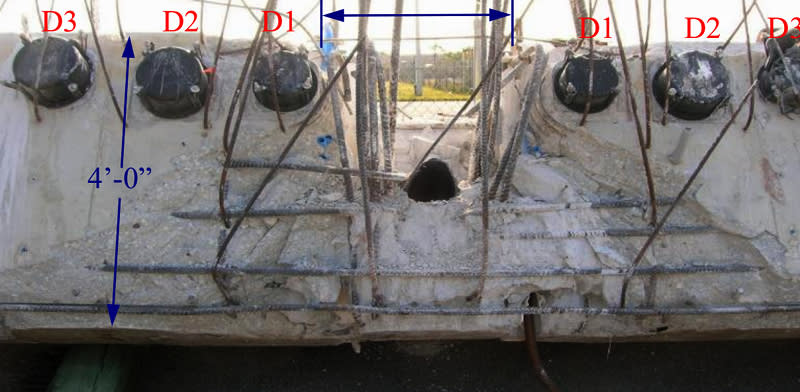
Thanks for putting that into words for me. I struggle with the rebar placement in this project. The dissymmetry in the diaphragm is yet another example.

Rebar_Dissymetry_t5ggi0.jpg
 
Earth314159, I think you underestimate the complications of a concrete truss design in general, not to speak of a post-tensioned truss with construction joints. I would not attempt such a design, even though I am generally a "concrete guy".
 
Hokie66 said:
Earth314159, I think you underestimate the complications of a concrete truss design in general, not to speak of a post-tensioned truss with construction joints. I would not attempt such a design, even though I am generally a "concrete guy".

It might be a difficult design but I have actually done more complicated concrete designs myself (including the PT). Every concrete designer should be very well familiar with failure mechanisms that took place on this bridge. The only design aspects that concern me are the aero-elastic, unbalanced live load and torsional flexibility/frequency. The long term interaction with concrete creep and the tube stays could also be a mess to untangle. However, the component that failed was one of the more simple aspects of the bridge. You can literally get a good estimate of the horizontal shear and stress levels with quick hand calculations. Once you know that you have about 8MPa shear at the pour joint, you know there are going to be design issues.
 
I found it compelling that T Y Lin, a name synonymous with prestressed concrete, originally proposed a steel bridge. This was in the request for proposals. When the proposals came in, FIU gave the design-build contract to the contractor using Figg's design, based on aesthetics. Whether T Y Lin had any further input is unclear.
 
hokie66 (Structural) 30 Jul 19 21:31 said:
Whether T Y Lin had any further input is unclear.

According to the OSHA report, page 14, the selection committee was made up of FIU officials, the City of Sweetwater, and FDOT. TY Lin, which prepared the design criteria, wasn't a part of the selection committee.

Is is normal practice to not include someone with technical expertise?
 
I cannot imagine a typical case where those responsible for making the selection would have technical expertise.

There have been a number of times when I wished they did; too many times where being up against someone incompetent who tells a pleasing story that is obviously wrong but the selector "doesn't have time to hear more" or "doesn't want a lecture" on the topic; they want what they want and shed responsibility to those with the pencils to paper.

It's basically how division of labor has to work.

Licensing and lawsuits handle the rest and, considering the rarity of stupid disasters like this, those countermeasures seem to work.
 
sym said:
Any thoughts on a better way to pour so the web and deck act more like a single unit? (I'm not even sure that's the right question)

Square up the pour joint and make the diaphragm a foot thicker.
 
SFcharlie said:
Earth314159 Any thoughts on a better way to pour so the web and deck act more like a single unit? (I'm not even sure that's the right question)

There are multiple issues with the joints. The horizontal interface shear stress is too high at the pour joints (it is also too high at other joints and just not the one that failed). You also have issues with the transfer of the vertical loads from the deck to the diagonals. The other issue is there is a functional architectural problem with the diagonals. When an architect or designer gives you a column projecting at an angle, you have to make sure people don't walk into the diagonal. It is especially important nowadays with people using cell phones. To solve all these issues, you fundamentally want a bigger base at the diagonals (a longer base in the direction of the bridge span). You flare out the diagonals parallel to the direction of the bridge (you can keep the 1'-9" width the same or perhaps make it a bit wider). People don't utilize the space below the diagonal anyways since you don't want to walk under a diagonal when you are close to the base (otherwise you hit your head). Architects think diagonal/sloped columns look cool so this is a common issue that I have encountered. We end up putting the columns on pedestals or coming up with some other solution.

There are multiple ways of designing the flares and it depends of the aesthetics that people are looking for. You can even create a raised flat surface for planters.

Once you get the stresses to a lower level, you can fit more vertical steel in through the pour joint without getting congestion. This helps for both the horizontal shear and the vertical loads from the deck. You have to add horizontal steel in the flares to transfer the load more evenly across the pour joint below the flares.

To give you a feel of design and stress level, an interface shear with a 1MPa stress is simple and straightforward with minimal steel crossing the interface plan. 2MPa is a typical stress but needs to be considered and specifically detailed. 3MPa is manageable. 4MPa is more difficult to design. 5MPa is possible but congestion has to be carefully considered and you have to start considering higher strength concretes and steel. 8MPa is damn difficult (not practical at all) with extremely high concrete strengths and steel strength with very careful consideration for congestion. This is why we should be working in stresses and not forces. A stress level corresponds to certain design expectations. There is a more immediate understanding of the design issues.

I should also mention that other stress levels are high (such as the vertical shear at the web joints). With just a bit a re-sculpting of the shape, you can make a big difference to the design. The reshaping can also look better. It is my experience that structures that are proportioned with more realistic stress levels (not too high or too low), tend to look better.
 
Typical for many engineering projects, the selection process was two-step: first review of proposals, and second an interview. The first step was short-listing the five proposals that were submitted. If you are interested, the selection committee and their votes are in the scoresheet folder here: [URL unfurl="true"]http://facilities.fiu.edu/projects/BT-904-PRR.htm[/url] Interestingly, MCM was 3rd of the 5, and it appears only two were going to be interviewed. But after the ranking, the sealed cost proposals were opened and one (must have been GLF Construction) was over budget and was tossed out. Facchina and MCM remained and in the interview, MCM came out on top (scoresheet in the same link). Also if you are interested, the 4 other proposals are on the FIU site, but the MCM proposal can be found at the FDOT site [URL unfurl="true"]https://www.fdot.gov/info/co/record.shtm[/url] as well as the pre-proposal presentation.
 
hokie said:
The deck shortened due to shrinkage and applied compression, and that shortening was resisted by the inclined webs. Cracking resulted.

What are you basing that on? The report said cracking was noticed after shoring was removed.
 
Just throwing this out here. Looking at the truss members & the top of the canopy, both these surfaces appear to have received a topical application of a TiO2 coating. It kind of suggests that, if the client is expecting a uniform white appearance, then $300/cubic yard specialty white cement & TiO2 concrete is not really the way to get both an esthetic & environmental finish. I would hazard that a TiO2 coating of the bridge would have been cheaper and had it been applied to the underside of the bridge; the bridge would have sat on the temporary shores longer. I think the TiO2 concrete was the one contribution from FIU's ABC program.
 
hokie66 said:
This was reported by several sources.

Where does it say the cracks were caused by the PT shortening of the deck? I did a quick read of the article and couldn't find anything.

It doesn't make a lot of sense to me. In a determinant truss, the PT would not have introduced any member forces in the diagonals. The canopy would have to have a fairly high bending stiffness for the deck shortening to cause a lot of force in the diagonals and shear at the pour joints. The shear predominantly comes from the gravity load.
 
Tomfh said:
Square up the pour joint and make the diaphragm a foot thicker.

What is your thinking on making the diaphragm a foot thicker? Perhaps I am misunderstanding what you are proposing and why.
 
Earth314159 said:
There are multiple ways of designing the flares and it depends of the aesthetics that people are looking for. You can even create a raised flat surface for planters.
Thank you for your thoughtful answer.
(...guess FIU would have had to issue bump caps...)

SF Charlie
Eng-Tips.com Forum Policies
 
earth said:
What is your thinking on making the diaphragm a foot thicker? Perhaps I am misunderstanding what you are proposing and why

I meant a foot wider, to increase the horizontal thickness.

In my view there was failure of the cold joint for the first 100mm or so, and beyond that it's an overall concrete punching failure thru the diaphragm. If the diagram was 3 foot thick not 2 foot thick it couldn't punch out the way it did.
 
hokie said:
This was reported by several sources.

It mentions the bridge was supported each end, i.e. gravity loading.

I agree with Earth that the PT and shrinkage shortening would not induce sufficient loads to fail the node. The canopy and member 12 are not stiff enough to resist the shortening.
 
Status
Not open for further replies.

Part and Inventory Search

Sponsor