Continue to Site

Eng-Tips is the largest engineering community on the Internet

Intelligent Work Forums for Engineering Professionals

  • Congratulations KootK on being selected by the Eng-Tips community for having the most helpful posts in the forums last week. Way to Go!

Bridge failure near Albany NY 15

Status
Not open for further replies.

bridgebuster

Active member
Jun 27, 1999
3,964
I think they forgot some stiffeners [sad]

Picture1_tzflwq.png


Link
 
Replies continue below

Recommended for you

Abutments? Piers?
Did you mean supports?
Did you mean retaining walls?
Support columns may have possibly been added between the sidewalk ans the roadway similar to the supports of the original span.

A question for the structural guys;
Could the one buckled panel be replaced with a panel that is thick enough to carry the load?
If so, that would be the quickest, and cheapest fix.

--------------------
Ohm's law
Not just a good idea;
It's the LAW!
 
"Is there a reasonable suggestion to "modifying the abutments" when those are what is holding back the walls of the cut?"

"If you don't figure it out for yourself it won't mean much."


For other folks reading this: "Provide a 3-foot minimum clearance width for continuous passage; if a sidewalk is less than 5 feet in width, provide passing areas of 5 feet by 5 feet at intervals no farther than 200 feet apart"

Since the abutments are about 120' long, then the required passing areas could be placed outside of that range, in the retaining walls. And ADA compliance would be attained. Thus the abutments would not have to be modified.


spsalso
 
To me, the best design would have been to design a normal girder bridge to span the longer distance. Then, add on a raised section of girder in the middle, mimicking the look of the old bridge. (this would be cosmetic only) Yes, the overall height would be higher than the original lower girder end spans, but it would 'pay homage' to the original design, and could have been built to actually stay up.
 
Odd - my state says:

The minimum continuous and unobstructed clear width of a pedestrian access route shall be 4.0 feet, exclusive of the width of the curb.

and

Exception: an unaltered, existing sidewalk shall be 3 feet wide minimum and shall provide 5 foot x 5 foot passing spaces at intervals of 200 feet maximum.

But this sidewalk isn't unaltered. It's brand new.
 
waross - they are labeled abutments on the plans I linked to. They resisted the ground pressure from repeated locomotive passages.
 
Stupid design. Top element from thin section should continue at least into next panel or two of the taller section.

I can see that right away, and my study was in thermo and fluid flow!!
 
I just replaced a broken trigger in my vacuum. It broke right where the section necked down in depth, conveniently located at the highest stress point of the trigger body. I noticed there was also a stiffener right NEXT to the change in depth, which helped ensure it would fail at the weak point. Perhaps a talented engineer was implementing engineered obsolescence into their product per corporate guidelines. Or maybe it was just an unfortunate oversight.

The bridge designer did the same thing and put stiffeners right NEXT to the step down in section depth. Do you guys think the stiffeners immediately adjacent to the step down helped promote buckling at that section, or the buckling strength at that section is equal to or greater than if there were no stiffeners at all?
 
FacEngrPE (Mechanical) 14 Jul 23 22:53 said:
The compression forces will not stay in the upper flange S bend. It would be quite difficult to design reinforcement that would work here.
The top flange on the lower step presses horizontally into the taller web element. This would require radiating elements to distribute the force, primarily to the top flange of the deeper center beam section.
 
Looking at the MJELS propaganda brochures it certainly seems they should have been capable.

Something went way wrong somewhere.

The problem with sloppy work is that the supply FAR EXCEEDS the demand
 
When I did a search for the company, I found they were members of MANY clubs/organizations/associations.

I did not find many examples of what they produced. I do recall that they interviewed a bunch of people in some small town for a project, and the locals were impressed that they "cared".

This organization is reminiscent of OceanGate.

I wonder if there's also a Big Cheese who knows Everything.


spsalso
 
Let's not assume too much about the organisations involved, based on this one project. Stuff happens in even the best firms.
 
Stuff like this? And it gets delivered to the customer?

Yikes!


spsalso
 
Could even be an issue with the span builder or constructor, not the designers. Around a year ago we had a 44ft and a 22ft span show up as a single 66ft span. That was a long haul back to the manufacturer to be cut apart and modified to match the approved plans. Reputable manufacturer, but details were getting overlooked in the shop on almost every span and a lot of field work was done to get around it. 2.5" flanges on 0.5" thick webs like is on most steel rail bridges going back 130 years. They look thin, but they work.

The lack of columns in under the span in construction verus the proposed plans to me indicates a failure on the constructors.
 
"The lack of columns in under the span in construction verus the proposed plans to me indicates a failure on the constructors."

The plans, linked above by 3DDave, show the comment: "EXISTING STEEL COLUMNS TO BE REMOVED (TYP)"

I don't understand your comment. The failure would appear to be in the design, not the execution.


spsalso
 
Memory error on my part. Shoe has firmly been inserted into mouth.
 
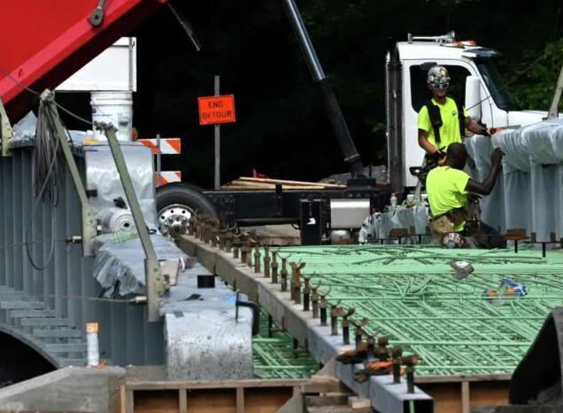
Looking at the photo before concrete was poured, this is a pretty impressive amount of re-bar.

The bridge is also slightly curved. Was the intent for the concrete to essentially be the main supporting structure and the side bits decoration?

So during construction it would need the bridge temporarily supported? Which didn't happen on the side which bent? won't be the first time that loads and stresses during construction don't get looked at properly.

It's interesting that on the other side there are some steel supports between the bridge and the abutment / retaining wall.

Screenshot_2023-07-17_132602_sgrb8n.jpg


Remember - More details = better answers
Also: If you get a response it's polite to respond to it.
 
A fabrication error could be contributing to the failure. The rendering and elevation show a stiffener ~4" from both depth changes. What was fab'ed is different, maybe ~8" at one end and ~3' at the other.
 
I'd like to know which structural analysis methods/tools they used since this structure was never going to work.
 
Sym.P.Lee

But but but the last one stood for 100 years[!]

(I know about the supports but maybe the junior engineer assigned to this was never told....)

Remember - More details = better answers
Also: If you get a response it's polite to respond to it.
 
Status
Not open for further replies.

Part and Inventory Search

Sponsor