Continue to Site

Eng-Tips is the largest engineering community on the Internet

Intelligent Work Forums for Engineering Professionals

  • Congratulations KootK on being selected by the Eng-Tips community for having the most helpful posts in the forums last week. Way to Go!

Miami Pedestrian Bridge, Part IV 74

Status
Not open for further replies.
SheerForceEng
"I must stress again that this is not a complex sturcture and indeed a truss is something we all learn in Engineering 101 at university."

Totally disagree and possibly this type of off the cuff thinking is why we are now even discussing this failure. I believe that a very experienced engineering firm may have neglected some of the reasons this structure as designed is more complex that they thought. Shear lag problems are much more complex than taking a 45 deg or other angle to see how many strands might be effective in providing resistance in the bottom chord near the sockets. I do agree that some simple hand calculations would lead me to suspect that there was a problem at the truss joints with the chords and do more detailed checking. Don't require a powerful computer running complex data input to adequately deign a complex structure. Many complex structures were successfully designed and erected with only slide rules available; I worked on many of these in my very early years.

In Part II and Part III I summarized why this structure as far as stress analysis is far more complex that a simple pin jointed truss.

 
saikee119 (Structural) said:
The question now is has this connection been adequately designed or not overlooked.
I see single asymmetrical concrete truss and ABC as not the best choices for a bridge.
All must be perfect designed and executed. Full collapse was half second only when bridge was looking safe and stable like a rock.
 
appster said:
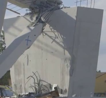
I believe that the picture of the bottom deck in Incentives post above clearly shows that the tendons in the deck or the deck itself did not blow "out the back" but that section 11 and 2 sheared cleanly off at the deck due to inadequate shear capacity.

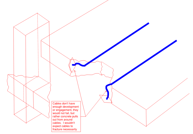
I agree with your first comment regarding the cables blowing out the back. I don't think the cables went anywhere at all, but rather the concrete would have blown out sideways as this is where the net load direction is headed. Because the cables aren't adequately embeded in the concrete its a "pull out failure" rather than a tendon breakage failure.

Be carefull when talking about shear. Even with temperature effects and shrinkage taken into consideration, a well detailed and designed truss should have nominal shear/moment in its members especially when compared to the tension/compressions experienced in the members themselves. Therefore the primary forces acting within the members is tension or compression with some incidental shears and moments thrown in (again if detailed and designed properly!!)

I know this is semantics but regarding shear "failure", if member 11 and 12 were to shear off the deck (say the top surface of the bottom deck is the shear plane) then this is a very large cross sectional area for shear to act over. With "cone pull-out failure" the concrete is actually acting in a combination of shear and tension, as we all know concrete behaves terribly in tension, so the capacity of this failure mechanism is much lower than say pure shear of the cross-sectional areas from 11 and 12 interface with the deck.

However at this point I believe we are splitting hairs and there may be elements of both failure mechanisms (pure shear of members 11/12 as well as pull out cone failure) occurring, especially when yielding occurs and the system tries to find other load paths as things turn south.

The trouble with looking at the failed structure only is that it doesn't give a good indication of what gave way first, other failure mechanisms would come into play, but generally after the first domino has been knocked over so to speak. This is where the analysis of the as-built structure (in theoretical terms) will be key to the investigation... numbers don't lie, images can.

pull_out_1_l2pqr9.png

Pull_out_2_wfdnxf.png

Pull_out_3_cmco0l.png
 
Thanks all for the continuing discussion. A few responses:

Meerkat 007 said:
24 Mar 18 23:47 3D model of 11-12-deck joint superimposed on the NTSB rubble photo

Thanks Meerkat, excellent visualization. As we have been deducing here, based on the positions of the white pipes/sleeves adjacent to #12, my original visualization of that area had 11 and 12 drawn too large. It was on my mind to revise it, but yours is better.

VolsCE84 said:
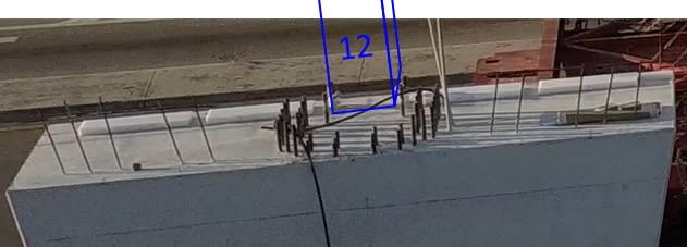
24 Mar 18 19:22 the area you have blocked out in blue.
See Meerkat 007's better 3D model which shows 11 as 12 to be smaller size than in my earlier annotated photo. I agree with your main discussion.

SheerForceEng said:
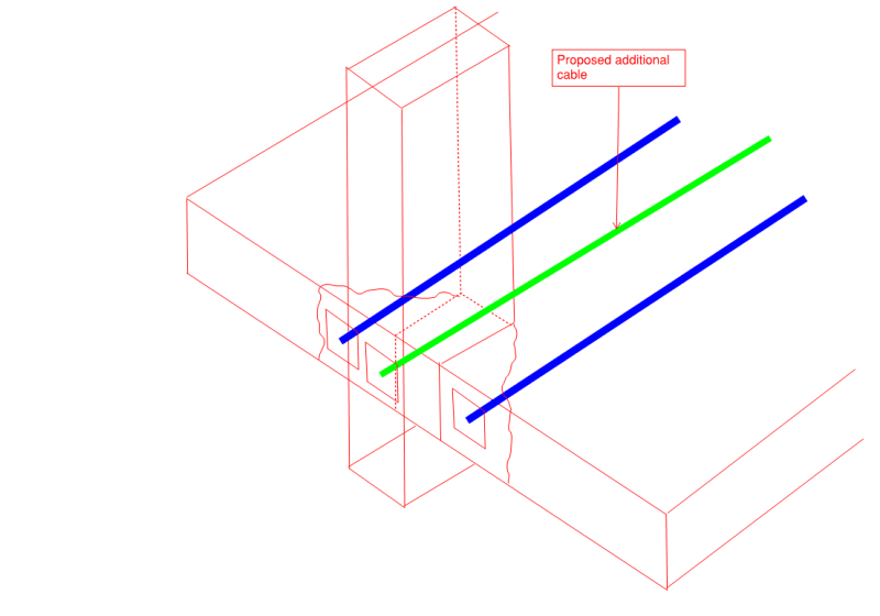
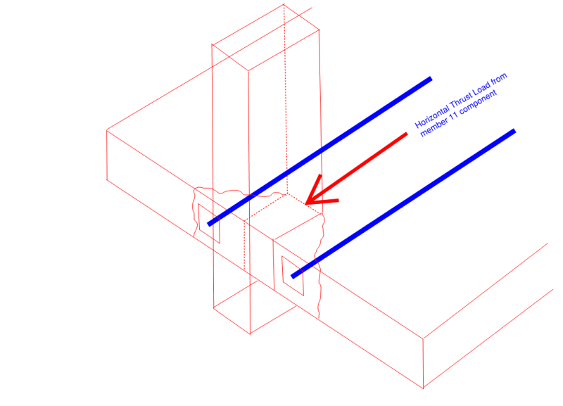
24 Mar 18 22:40 see right at the very bottom for my solution and what I would expect for the joint detailing.
Responding to my questions to structural engs about how they would expect a joint like 11-12-deck might be designed to work, specifically how stress finds its way from #11 to the deck's tendons.

Thanks for that discussion, very informative.

Lnewqban said:
24 Mar 18 14:05 Suggests adding a "horizontal member" with PT between 11 and 10 at deck level..
This parallels the solution suggested by SheerForceEng.
 
appster said:
Totally disagree and possibly this type of off the cuff thinking is why we are now even discussing this failure. I believe that a very experienced engineering firm may have neglected some of the reasons this structure as designed is more complex that they thought. Shear lag problems are much more complex than taking a 45 deg or other angle to see how many strands might be effective in providing resistance in the bottom chord near the sockets.

I agree with your sentiment, however if you think about it in reverse, the harder and more technical it is to analyse, and the more analysis you need to prove that it works, the harder it is to construct.

I don't believe it is complex or difficult at all to realise that you have tension in the bottom chord and therefore need to develop this tension from the node into the member. This seems very logical and as I said, not complex in any way shape or form.

A more rigorous analysis I agree would be able to justify certain things quite well but if you put it into perspective, what would the designer be wanting to achieve by trying to justify not putting tension cables within the node of a truss where its required? Ok you can analyse it and maybe justify that it could work but then your relying on the builder getting the cable in the exact position you are assuming because once you go down that path 100mm either way with the cable placement can make all the difference. By living life that far on the edge you start to rely more and more on the ability of the builder to get it spot on in the as-built form. This is a structure with no redundancy as we have already speculated, to further reduce this redundancy by not adopting standard, simple detailing practices is flying too close to the sun imo.

Engineers shouldnt live in bubbles in the office and over complicate things with the expectation that it can be built exactly the same way in the real world especially if things get congested with reinforcement placement.

Some engineers also have a tendency to "overanalyse" by way of computer software and FEA modelling, to the point of relying on these tools more than they should (thus overcomplicating things). I have no doubt that you can input all this data for the members into a computer model and it will all work (in theory on the computer scree). But then there is a point where you need to extract it from your computer model and put it onto drawings and get it to work in the real world. This is where detailing of the connections is key and basic engineering principles need to prevail (not complicated).


If you look at Meerkat007s latest drawing post you can see that the combined footprint of member 12 and 11 at the deck face is about double the sheer footprint of 12 alone. I have been saying from the beginning that shear is the failure mode and that the joint at no. 11 and 12 was the culprit. If the structure had been properly analyzed and required shear capacity provided in whatever form between the web and flanges this failure would not have occurred when it did.

If the deck concrete "blew out the back" as you argue then the 2 tendons you talk with about 22" of elongation would crush the grout around them and be found in contact with the deck concrete somewhere between the abutment and the new face of the broken concrete deck, do not see any evidence of this in the pictures of the failed back and foundation.

Just one further comment. If the structure was loaded eccentrically with half LL on one side of the walkway and full LL on the other (big crowd on one side of the bridge) I think it would have failed later in torsion due to excessive shear forces and lateral bending in the web members. A failure later could have been even more tragic due to very high loss of life. Looking at the bridge I am fairly certain that imbalance in load laterally across the bridge deck was not even considered in the design; a section with much better torsional resistance would be required.

A design may be ill conceived but if the structure is designed properly then even an ill conceived design as far as economics and other factors can still be implemented.
 
PilTraces_vhodqo.jpg


Scuffing is visible only on the outside and not in the middle. Would that be indicative of cone pullout failure?
 

INCENTIVE,

I don't think there was a blow out. When a reinforced or pre-stressed concrete member fails broken concrete will be sprayed in the vicinity.

The collapsed bridge has No. 11 and 12 members separated from their connection points with the walkway. A large number of people here now think the bottom of Member 11 & 12 has suffered a horizontal shear failure which could push these two members outward at exactly the point the bridge protruded at the moment of collapse.

It is a simple exercise in statics that the sloping member No. 11 has one of the highest axial compression in the bridge. Therefore its vertical component has to be resisted by the pier/foundation while the horizontal component must be resisted by stretching the walkway deck. The deck is sufficiently strong but if sufficient rebar has not been provided at the connection Member 11 can overcome the shear resistance of the connection, become detached and deflect to the north. Once Member 11 isn't carrying out its structural duty the whole bridge will collapse. There is a Internet simulation showing the bridge will collapse the way it did if member 11 were withdrawn.
 
Is member 12 important other than to support a section of the canopy?
Would the truss not work the same if member 12 and the last section of the canopy were not built?
What is important is the connection between member 11 and the deck. This connection forms part of the truss triangle.
Most of the damage to members 11 and 12 may have been done by the deck pulling away, after the initial failure was initiated.
A question to ponder now:
Did a partial crush failure of member 11 lead to the failure of the deck, or did the deck fail first and in falling do all the damage to members 11 and 12.
If the 11-12 connection had been blown out very much, would there not be a tendency for it to be hooked behind the support column instead of resting on top of the column?

Re the pipe stays. On cold days when there may be little pedestrian traffic and what traffic there is may be hurrying across the bridge to a warmer place the pipe stays will be contracted and will be giving the most support.
On hot sunny days, when traffic may be heavier and when pedestrians are more likely to linger on the bridge, the pipes will be expanded the most by the heat and will be providing the least support.

I wonder if the upper PT rod in member 11 was removed after it was relieved. Is it visible in any of the pictures?
Maybe the stays were intended to sag a little on hot days?

Bill
--------------------
"Why not the best?"
Jimmy Carter
 
appster: would you mind revisting your last few posts and checking the numbering you are using for members? I'm pretty sure each time you write "2" or "22" you actually mean "12", no?
 
Is there a "bow string" analogy here?
Could increased tension in member 11 act as a bow string and cause an increased down force on member 10 which in turn would lead to increased loading on the deck?
Could this increased force have caused the initial failure of the deck, rather than a failure of connection between the deck and members 11 and 12?

Bill
--------------------
"Why not the best?"
Jimmy Carter
 
waross said:
If the 11-12 connection had been blown out very much, would there not be a tendency for it to be hooked behind the support column instead of resting on top of the column?

No I beleive the node itself (intersection of 11, 12 and deck) would stay in place and not move.

Instead, once cone failure occurs, the bottom deck would tend to pull inwards towards the centre of the truss. Bare in mind that the bottom chord is in tension and is somewhat stretched, once connection with the support node is compromised, it wants to head away from the node becuase it wants to shorten and sling back to a non-stretched state, the node could stay where it is (hence why it remained on top of the support pier).

Also the entire truss is quite adequately supported laterally at its other end, meaning that for the vertical member 12 to end up on the outside of the support column would meam that it would have to pull the whole truss with it and the support at the other end as well to achieve this outcome.

 
SheerForceEng,

Your assumed shear failure is different from mine. The deck is highly stressed in both directions but the truss middle section is not. Therefore either the shear stress path was as you shown in the sketches in a homogeneous concrete mass or selectively along path least resistance found at the combined cross section of No. 11 & 12 plus the back end of Member 12 failure by tension with the end beam.

Member 12 and its canopy do not contribute much to the load carrying capacity of the bridge and can be regarded as redundant structurally. However there were 4 large diameter plastic ducts cast on either side of Member 12 and some members here already questioned about its effect in weakening the shear capacity of the concrete perimeter of No 12. There seems to be ample reinforcing steel still attached between Member 11 & 12 but little can be seen with the walkway deck. It is possible Member 11 & 12 sheared off together because being in a L shape the Member 12 with canopy is unlikely to offer much bending and axial restraint against Member 11 to shear outward.
 
Even with what I'm about to say, I don't think any particular initial collapse-starting scenario is the outright winner. There are too many variables and unknowns (to us) at this stage. That said...

Any scenario has to explain how the bottom end of #11 and #12 managed to remain on the top of the pier when the deck fell/dragged off the pier.

Members 11 and 12 were not only connected to the deck and end beam, but they should have been connected extremely strongly, for several reasons:

1. To contain #11's longitudinal force, which amounts to a large horizontal force, plus a vertical force that amounts to half the weight of the bridge.

2. That vertical force does not even transmit directly down to the pier:
gwfiu_20180324a_05_floating_12_yx2f2v.jpg

gwfiu_20180324a_06_floating_12_watuss.jpg


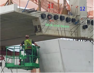
The end beam of the deck, which is integral with the base of #12, rests on nylon/teflon blocks, presumably to permit some sliding to accommodate positioning or expansion/contraction. These blocks are outboard of #12, so #12 is essentially suspended above the pier, and that 12-11-beam-deck joint should be strong enough, in multiple directions, to accomplish that.

Yet somehow, before the deck falls, #12+#11's friction with the pier, to which it was previously unconnected, proves strong enough to overcome #12-11's attachment to the end beam and deck.

I think this argues in favor of #11-12 first becoming disconnected from the deck/end-beam, dropping an inch or two onto the pier, and then the deck sliding off the top of the pier. And therefore that actually #11-#12 was not sufficiently connected to deck+end-beam.
 
Another conjecture:
About the only part of the 11-12 connection remaining with the deck is the lower PT rod.
Possibly the crew did everything correctly and removed the nut without incident.
However, when they then relieved the tension, the strength of the main connection between 11-12 and the deck was lost.
As the deck dropped, the bottom ends of both 11 and 12 were destroyed.


Bill
--------------------
"Why not the best?"
Jimmy Carter
 
Using the approximate footprint of 11 and 12 combined from the picture which is about 60" long and 22" wide the interface shear area is about 1584in2. The approximate horizontal component to the thrust in 11 is 1520 kips. Nominal shear stress then is about 1.0 KSI or 1000 psi at the web bottom flange interface. This is a scary number when you consider that AASHTO for Horizontal Interface Shear allows max. 80 psi x bd with no shear reinforcing, 350 psi x bd where minimum with minimum vertical ties (shear reinforcing) are provided and 330 x bd + 0.4 A fy x dv/spacing

If we use a simple value of square root of F'c (an old value) then assuming 5000 psi concrete we come up with 70 psi for plain concrete. Obviously the concrete needs full mild steel reinforcing to transfer the shear load, I do not see that anywhere in this structure at the web members, either at the deck or in the caps and canopy.

Adding approximately 500 k more in horizontal component for live load still to be provided for, I really don't know what the designers were thinking.

Just to take this one step further I have estimated the total shear area using the section of the deck shown to the tensioning duct on each side and then then from the ducts at 90 degrees to sloped bottom edge of the deck as the shear plane as shown. With a total perimeter of about 15' or 180" and shear plane through the deck of about 22" the total shear area is about 3960 sq. in. If the DL hor. shear in 11 is about 1500 kips then the stress is 380 psi horizontally and 950/3960 = 240 psi vertically requiring serious shear reinforcing and with DL+LL (2000 k hor.) approximately 505 psi and (950+317)/3960 = 320 psi vertically. Still have no idea what they were thinking.

[URL unfurl="true"]https://res.cloudinary.com/engineering-com/image/upload/v1521955954/tips/part_section_ym7zqf.pdf[/url]
 
gwideman said:
Even with what I'm about to say, I don't think any particular initial collapse-starting scenario is the outright winner. There are too many variables and unknowns (to us) at this stage.

IMHO, you are correct; we still need additional information to identify the initiation of the collapse. We have, I think, a reasonable location.

Dik
 
INCENTIVE said:
Is it the consensus that the concrete seen protruding half a second before the collapse is just the camera angle/illusion?

Looks like the dashcam vehicle was slowed to a crawl. The viewing angle didn't change enough in the 0.16 seconds to create that illusion. Even at 10mph, 0.16 sec is just 2 ft 4 inches.

old jim
 
Pull_out_2_wfdnxf.png


Pretty much this as far as I am concerned given the available information. Also the proposed solution seems like an adequate solution that would have prevented this tragedy.

That said on so many levels already discussed this could have been avoided. Starting from building a brittle truss that seems to prioritise aesthetics over safe structural design. Nothing wrong with asthetics, but don't let it interfere so much that you are skating the thin edge of structural viability. (And in this case it skated on the wrong side of that edge.)
 
I'm a little shocked to learn that a 70 foot span is considered a long bridge. That's just typical overpass over 4-5 lanes highway.
So, assuming that the designers were guided by the quoted codes and design guides, the maximum safety factor was just 1.5, and it was a temporary condition.
I think that the major problem was the transfer of the horizontal component at the intersection of #10 and #11 to the canopy. Please note, that the canopy was post-tensioned longitudinally, but not transverse, which in my opinion is critical, as this severely reduces the shear capacity of the connection.
As the entire blister was cleary rip out of the canopy, almost intact, the stresses at the perimeter of it are critical. The force of approximately of 1,500 kips (max 10% off) shall be transferred from #11 to the canopy at this node. In the detailed analyses we may disregard the blister, and just use the area of the intersecting #11 and #10 with the canopy as effective. On top of it, the post-tensioning of the canopy shall be added to correctly assess the 3-D stresses at critical intersection.
The cracks, which we do not know the details about at this stage, likely formed at the perimeter of the blister. These should be longitudinal or herringbone like, depends of the mode of failure of concrete, but indicative of what's happening.
The bridge was apparently designed up the code requirements, so who is to blame?
There is no provision in AASHTO for 3-D stress analysis, and no guideline how to assess complex stress case. So, the designer was left with the code, and I'm pretty sure adhere to it.
 
Status
Not open for further replies.

Part and Inventory Search

Sponsor